A flue gas treatment tower and treatment system

A flue gas treatment and treatment tower technology, which is applied in closed-circuit television systems, dispersed particle separation, chemical instruments and methods, etc. Cleanliness, improve overall operational reliability, ensure overall efficiency and output effect

Active Publication Date: 2018-03-16
万亨
View PDF7 Cites 0 Cited by
  • Summary
  • Abstract
  • Description
  • Claims
  • Application Information

AI Technical Summary

Problems solved by technology

[0003] During the production process, due to the characteristics of the flue gas desulfurization environmental protection facilities, the operating medium is highly corrosive, abrasive, easy to accumulate dust, easy to deposit, easy to scale, and the working conditions are constantly changing; there are many fault points and high frequency of repair and maintenance. ; Moreover, the relationship between the operating parameters of the above-mentioned environmental protection facilities is complicated, and the operation adjustment is difficult
As a result, the above-mentioned environmental protection facilities often have the following problems of output decline, low overall efficiency and system failure: (1) The heat exchange elements in the flue gas heat exchanger are fouled and blocked, resulting in a decrease in system output; (2) The spray in the absorption tower Blockage or damage of shower pipes and nozzles, resulting in a decrease in desulfurization efficiency; (3) Blockage or collapse of the demister in the absorption tower, resulting in "gypsum rain" in the system exhaust, and even forced shutdown of the system; (4) Desulfurization smoke Excessive deposits in the horizontal section of the duct lead to deformation of the flue duct and cause the desulfurization baffle door to fail to open and close normally, which affects safe production in severe cases; (5) The liquid level sensing data in the absorption tower is inaccurate, resulting in system processing decrease, and the overflow of liquid in the tower causes safety accidents, etc.
This will inevitably affect the operation reliability and stability of the entire set of facilities and the entire set of coal-fired units, and will have a negative impact on the economic and environmental protection of the environmental protection facilities. In severe cases, safety production accidents will occur
In addition, even when the above-mentioned environmental protection facilities are out of operation, there are still places where staff cannot enter, such as flue gas leakage in the desulfurization flue, flue gas heat exchanger, and absorption tower, and the isolation is not clean; the spraying in the absorption tower Pipes and nozzles cannot be directly inspected, and scaffolding must be built, which hinders the timely and effective inspection work
[0005] It is noted that in recent years, two invention patents have carried out related research in this field: the first patent (patent number ZL201120235026.6) discloses a "content monitoring device for wet flue gas desulfurization facilities", mainly a A detection instrument with a video probe is designed on the top of the probe rod. This instrument needs to be manually penetrated into the interior of the facility through the existing hand hole or manhole door of the desulfurization facility. Poor, and operators are vulnerable to harmful gas spilled from desulfurization facilities
Another patent (Patent No. ZL201220353373.3) discloses "a wet flue gas desulfurization device". This patent mainly designs a special video camera, video encoder, display, etc. inside the wet flue gas desulfurization device. The video equipment used in the device is fixed and cannot be moved, so it cannot be moved to the interior of the desulfurization device for in-depth, approaching, contact observation and visitation, and there is no mechanical arm for corresponding dredging, repairing and other maintenance functions

Method used


Image

  • A flue gas treatment tower and treatment system
  • A flue gas treatment tower and treatment system
  • A flue gas treatment tower and treatment system

Examples


Embodiment Construction

[0031] The present invention will be further described below in conjunction with the accompanying drawings.

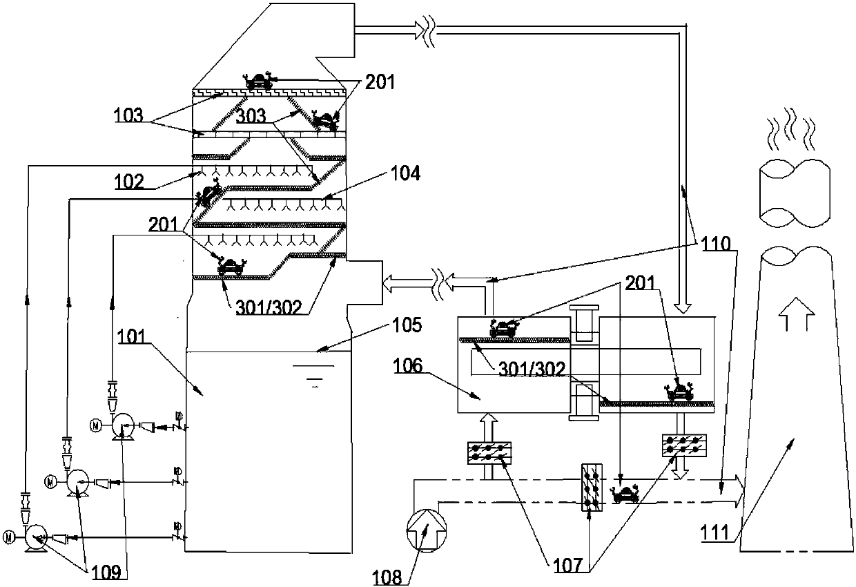
[0032] Such as figure 1 As shown, the present invention is a flue gas treatment tower and treatment system, wherein the treatment tower includes a tower body 101 with a flue gas inlet and a flue gas outlet, wherein the tower body can be an absorption tower, a desulfurization tower or a flue gas scrubber. A spray layer and an absorption layer are arranged in the tower body 101, and the spray layer and the absorption layer are located between the flue gas inlet and the flue gas outlet, wherein the spray layer is provided with a spray pipe 104, installed on the spray pipe There are nozzles 102 and the absorbing layer is provided with demisters 103 . In the tower body, there is also a treatment tower access channel, which is a continuous channel, including support beams 301, walkway platform 302, and climbing ladder or slope 303. The lower end of the treatment tower access ...


PUM


Abstract

The invention discloses a flue gas treatment tower and a treatment system. The flue gas treatment tower comprises a tower body with a flue gas inlet and a flue gas outlet, wherein a spraying layer and an absorbing layer are arranged in the tower body; a treatment tower overhauling channel is also arranged in the tower body; the treatment tower overhauling channel is arranged as a continuous channel and comprises a supporting beam, a footpath platform and a ladder or slope; the lower end of the treatment tower overhauling channel is located in an area of the spraying layer; the upper end of the treatment tower overhauling channel is located in the area of the absorbing layer; a moveable detector moving on the treatment tower overhauling channel is arranged on the treatment tower overhauling channel; the moveable detector comprises a video capturing device used for monitoring and a mechanical arm used for repairing. The flue gas treatment tower can greatly increase the overall running reliability of desulfuration environment-friendly facility and coal-fired unit and can guarantee the overall running efficiency and labor, so that the purpose of safe, stable, economical and environment-friendly production is achieved and the ultralow emission effect of the environment-friendly facility and coal-fired unit can be practically realized.

Description

technical field [0001] The invention belongs to the intersection field of flue gas desulfurization environmental protection facilities and industrial robots, and furthermore is a flue gas desulfurization facility with mobile detection and maintenance functions. Background technique [0002] Flue gas desulfurization facilities are the main environmental protection devices for the prevention and control of air pollutants in my country, and are an important technical means for enterprises in industries such as electric power, steel, chemical, metallurgy, aluminum, and coal-fired heating to control sulfur dioxide emissions. With the increasing determination of the country on smog control and environmental protection, and the further strengthening of environmental protection supervision, the majority of coal-fired coal enterprises have been actively developing flue gas desulfurization environmental protection facilities and coal-fired units with local governments. Low emission" a...

Claims


Application Information

Patent Timeline
Patent Type & Authority Patents(China)
IPC IPC(8): B01D53/80B01D53/18B01D53/78B01D53/50H04N7/18
CPCB01D53/18B01D53/50B01D53/502B01D53/78B01D53/80B01D2251/404H04N7/18
Inventor 万亨
Owner 万亨
Why Eureka
Try Eureka