
Method for actuating inverters connected in parallel

An inverter-level, three-phase inverter technology, which is applied in the direction of instruments, electric variable adjustment, control/regulation systems, etc., can solve the problems of transmission rate limitation, error-prone system, etc., and achieve wiring cost reduction, The effect of a simple structure

Active Publication Date: 2016-08-10
SCHNEIDER ELECTRIC POWER DRIVES GMBH
View PDF2 Cites 3 Cited by
  • Summary
  • Abstract
  • Description
  • Claims
  • Application Information

AI Technical Summary

Problems solved by technology

Therefore, in practice, the number of inverter stages connected in parallel is strictly defined and limited to a few converters
Furthermore, as the number of parallel-connected inverters increases, the transmission paths to the central control unit also gradually become longer, so that together with the limited transmission rate of the measured data for the parallel transmission, the entire system is prone to There is also a significant increase in error
[0004] Therefore, for actuating parallel-connected inverter stages, light conductor connections are also used, but they again have disadvantages due to their temperature sensitivity
Furthermore, the outlay and costs of photoconductor-based manipulation are similar to those of conventional analog parallel manipulation
A similar situation applies to fieldbus systems, which also have disadvantages for actuating the switching elements of the inverter stage due to their limited transmission rates and sometimes high delay times

Method used


Image

  • Method for actuating inverters connected in parallel
  • Method for actuating inverters connected in parallel
  • Method for actuating inverters connected in parallel

Examples


Embodiment Construction

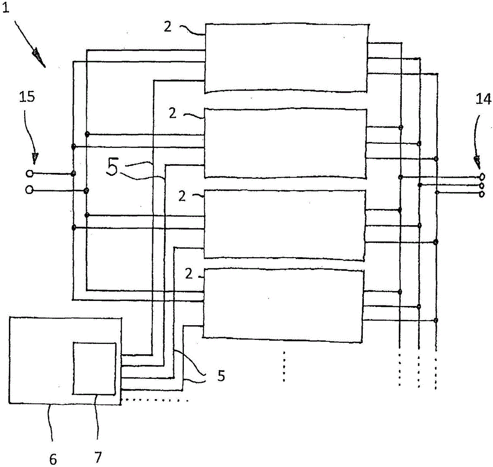
[0041] figure 1 An arrangement 1 is shown consisting of a plurality of parallel-connected inverter stages 2 having a common three-phase output 14 . At this output 14 the arrangement 1 supplies the desired output current. In the illustrated embodiment, a common input 15 of the inverter stages 2 is also shown, to which an input voltage is applied during operation.

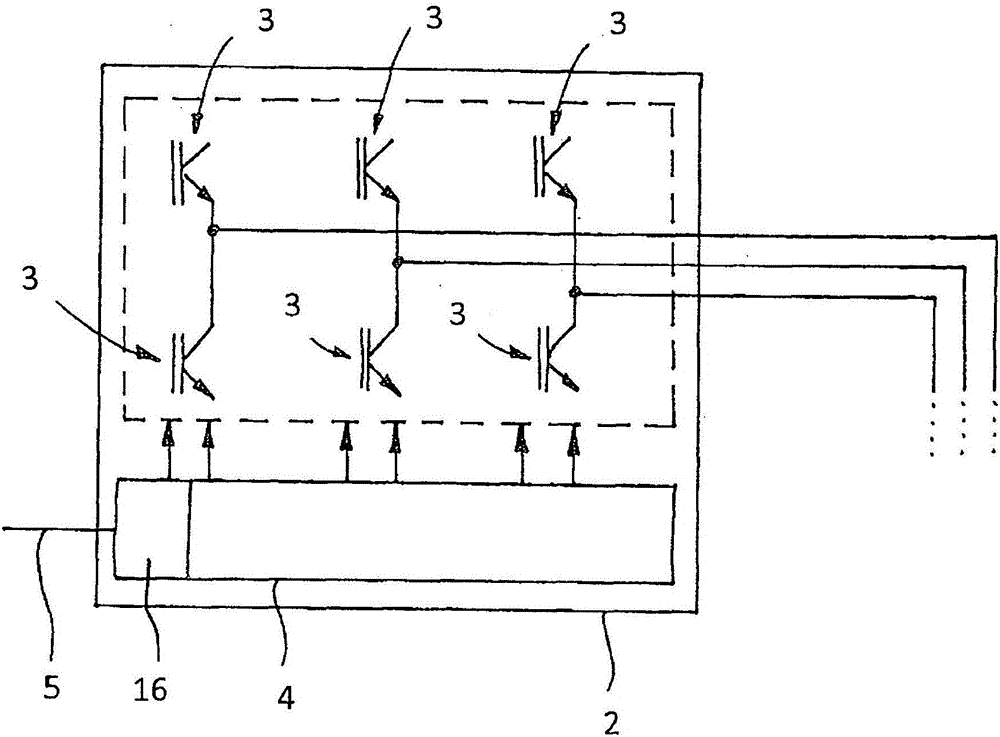
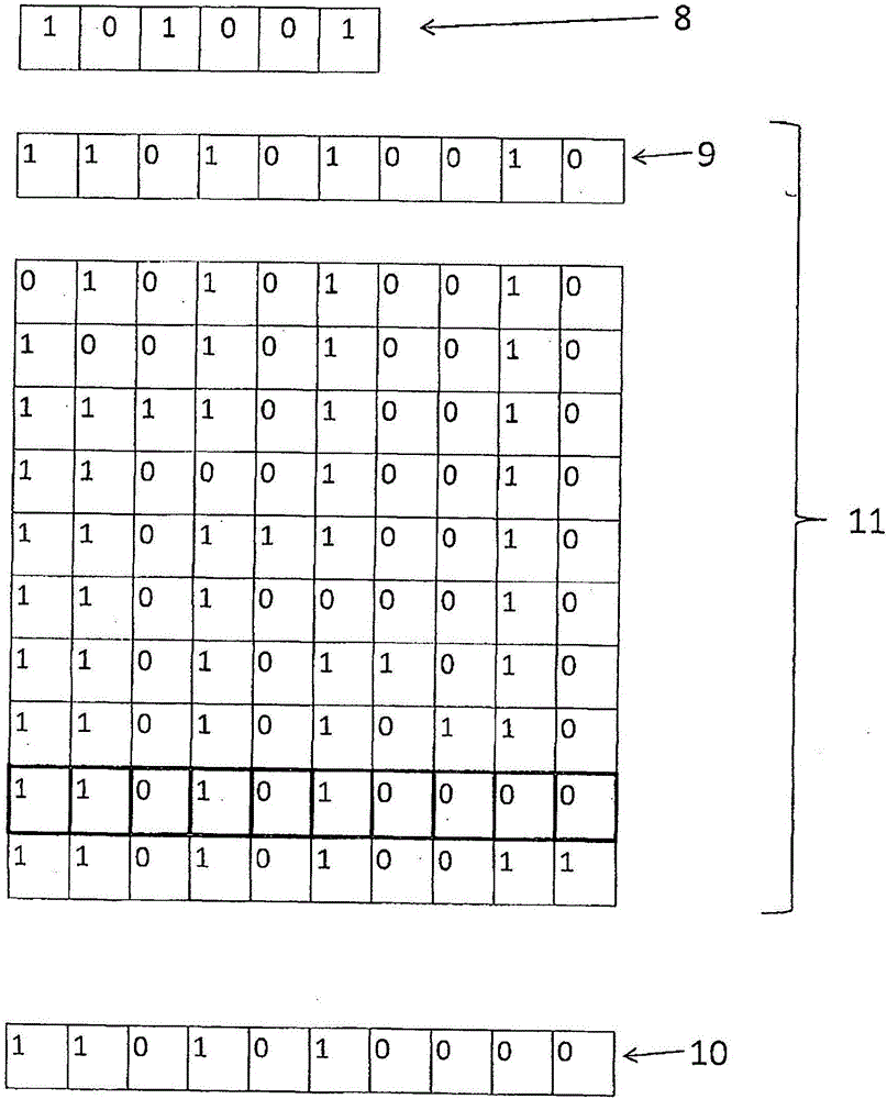
[0042] Each inverter stage 2 comprises six switching elements 3 each having two switching states ( figure 2 ), whereby the theoretical number of total switching states of the inverter stage 2 is given by all combination possibilities. In the case of six switching elements 3 (as in the figure 2 As clearly visible in the embodiment of ), resulting in 64 theoretically possible total switching states. These total switching states are reduced to 27 permissible general switching states, since there are also unreliable switching states which could lead to short circuits. The overall switching state of the inverter st...


PUM


Abstract

The invention relates to a method for actuating inverter stages (2) connected in parallel, wherein each inverter stage (2) comprises a plurality of switching elements (3), each having two switching states. In accordance with the invention, the actuation of the inverter stages (2) takes place via a central regulation unit (6), which is connected to each inverter stage (2) via a serial data transmission path (5). For the transmission of the selected switching states from the central regulation unit (6) to the corresponding inverter stage (2), measures are proposed firstly for ensuring safe operation of the inverter stages (2) via a multiplicity of switching operations and reliably avoiding functional impairments of the switching elements (3) owing to faulty actuation, but secondly for performing the actuation of the switching elements (3) of the inverter stages (2) also sufficiently quickly in order not to impair the quality of the output current formed by the inverter stage (2).

Description

technical field [0001] The invention relates to a method according to the preamble of claim 1 for actuating a number N of switching elements of a parallel-connected three-phase inverter stage and a corresponding method according to the preamble of claim 8 arrangement system, wherein each of the N switching elements of the inverter stage has two switching states respectively and the overall switching state of the inverter stage can be used as N by means of the switching states of its switching elements The switching state of the bit is determined by the combination of the bit sequence presentation, by switching the switching elements at the switching frequency one of the general switching states of the inverter stage selected from a certain number of permitted general switching states is achieved time sequence to form the desired output current of the inverter stage. Background technique [0002] A three-phase inverter stage is used to form the desired output current by corr...

Claims


Application Information

Patent Timeline
Patent Type & Authority Applications(China)
IPC IPC(8): H02M7/493
CPCG05F1/20H02M1/0845H02M7/53873H02M7/493H02M1/0012H02M7/537
Inventor R·费尔因格G·莱纳
Owner SCHNEIDER ELECTRIC POWER DRIVES GMBH
Learn More