
Frameless crystalline silicon cell completely-PID-resistant light assembly and cell panel

A crystalline silicon cell and module technology, applied in electrical components, circuits, photovoltaic power generation, etc., can solve the problems of inconvenient portability and transportation, service life not exceeding 20 years, efficiency degradation, etc., to improve convenience and transportability. , Increase anti-PID performance, reduce the effect of component thickness

Inactive Publication Date: 2016-08-10
董友强
View PDF4 Cites 4 Cited by
  • Summary
  • Abstract
  • Description
  • Claims
  • Application Information

AI Technical Summary

Problems solved by technology

The packaged photovoltaic modules need to be placed in the open air. After a period of use, the dust particles in the air will be adsorbed on the cover plate of the photovoltaic module, forming a light-blocking dust covering layer, thereby reducing the photoelectric conversion rate of the photovoltaic module, and at the same time, the large pieces are opaque The coverage of pollutants will also produce hot spot effect, which will lead to local high temperature of photovoltaic modules until they are burned and scrapped
It can be seen that the natural resistance of solar photovoltaic modules is poor, and long-term exposure to the air will cause problems such as attenuation of efficiency and difficulty in cleaning after the surface accumulates ash. Therefore, the photoelectric conversion efficiency of existing photovoltaic modules is low, and the service life generally cannot exceed 20 years
[0005] At the same time, the weight of existing conventional crystalline silicon components is about 20kg
The weight of the component itself limits its scope of application, and cannot meet actual needs in projects such as roofs with weak load-bearing capacity
Moreover, conventional crystalline silicon components are bulky, making them inconvenient to carry and transport

Method used


Image

  • Frameless crystalline silicon cell completely-PID-resistant light assembly and cell panel
  • Frameless crystalline silicon cell completely-PID-resistant light assembly and cell panel

Examples


Embodiment Construction

[0026] In order to enable those skilled in the art to better understand the technical solutions in the present invention, the technical solutions in the embodiments of the present invention will be clearly and completely described below in conjunction with the drawings in the embodiments of the present invention. Obviously, the described The embodiments are only some of the embodiments of the present invention, not all of them. Based on the embodiments of the present invention, all other embodiments obtained by persons of ordinary skill in the art without making creative efforts shall fall within the protection scope of the present invention.

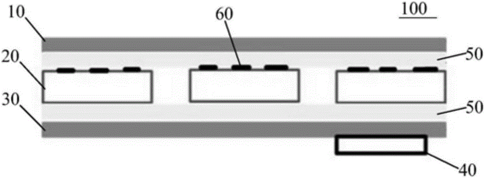
[0027] Such as figure 1 As shown, the frameless crystalline silicon battery of the present invention is completely anti-PID lightweight assembly 100 includes: a front glass 10, a battery sheet 20, a back plate 30 and a junction box 40, and the battery sheet 20 is located on the front glass 10 and between the backplane 30.

[0028] Whe...


PUM

PropertyMeasurementUnit
Thicknessaaaaaaaaaa
Thicknessaaaaaaaaaa

Abstract

The invention discloses a frameless crystalline silicon battery completely anti-PID lightweight assembly, including: a front glass, a cell, a back plate and a junction box, the battery is located between the front glass and the back plate; the front The plate glass is photovoltaic ultra-clear patterned glass with a thickness of 4.0-5.0 mm, and the surface of the front glass is coated with nano-titanium dioxide film. There are packaging material layers between them, the packaging material layer is polyolefin, the junction box is electrically connected to the battery sheet, and a wavelength conversion agent is mixed in the packaging material layer, and the wavelength conversion agent can convert invalid or low The effective wavelength of sunlight is shifted to the effective wavelength. The frameless crystalline silicon battery of the present invention is completely anti-PID, and the light-weight component abandons the aluminum frame, and the component can meet the load requirement of 5400pa without framing; and the component is completely resistant to PID, and reduces the weight of the component, reduces the thickness of the component, and reduces the manufacturing cost .

Description

technical field [0001] The invention relates to a crystalline silicon photovoltaic module, in particular to a frameless crystalline silicon battery completely anti-PID lightweight module and battery board. Background technique [0002] Crystalline silicon is divided into single crystal silicon, polycrystalline silicon, and amorphous silicon. Among them, monocrystalline silicon solar cells are currently the fastest developed type of solar cells. Its structure and production process have been finalized, and its products have been widely used in space and on the ground. [0003] The above-mentioned crystalline silicon can be used to make crystalline silicon photovoltaic modules. Studies have shown that the high voltage between the circuit in the crystalline silicon photovoltaic module and its grounded metal frame will cause the continuous attenuation of the photovoltaic performance of the module. There are many mechanisms causing such attenuation. For example, under the action...

Claims


Application Information

Patent Timeline
IPC IPC(8): H01L31/048H01L31/049
CPCY02E10/50H01L31/0488H01L31/049
Inventor 董友强
Owner 董友强
Learn More