Prognostic system and method for an electric coolant pump

a technology of electric coolant and diagnostic system, which is applied in the direction of engine cooling apparatus, positive displacement liquid engine, failure safe, etc., can solve the problems of low coolant flow rate, coolant leakage, overheating of the engine or connected system components, etc., and achieve the effect of facilitating the estimation of a numeric state of health

Active Publication Date: 2019-04-30
GM GLOBAL TECH OPERATIONS LLC
View PDF9 Cites 4 Cited by
  • Summary
  • Abstract
  • Description
  • Claims
  • Application Information

AI Technical Summary

Benefits of technology

[0002]Coolant pumps, colloquially known as water pumps, are the particular pumping devices used to circulate coolant in a closed fluid conduit loop. Inside the pump, rotating impeller blades move the coolant through the pump body and out to the engine. Mechanical coolant pumps are typically driven at engine speed by a rotating belt and engine-driven pulleys. Alternatively, an electrically-driven coolant pump allows the rotational speed of a pump motor to be electrically controlled independently of engine speed, e.g., using temperature-based feedback control. Electric coolant pumps are thus able to eliminate parasitic power losses, improve fuel economy, and reduce component weight relative to mechanical engine-driven coolant pumps.SUMMARY
[0003]A system and method are disclosed herein for performing a look-ahead prognosis of a thermal management system having an electric coolant pump. A non-limiting example embodiment of a top-level system that may benefit from the disclosed approach is a motor vehicle having an internal combustion engine. The methodology set forth herein is intended to facilitate estimation of a numeric state of health (SOH) of the thermal management system and its constituent components using available coolant pump sensor measurements. The pump thus acts as a “smart actuator” due to available closed-loop electrical feedback and sensor-based control signals, e.g., from a motor control processor resident within the coolant pump. The present approach, which can be implemented via an offboard and / or onboard controller in different embodiments, may be used to help identify and isolate developing system faults and quantify their relative severity before a hard failure has a chance to materialize.
[0004]An ongoing pump status mode diagnosed by the controllers may include a coolant flow rate. A low coolant flow rate may result from a coolant leak developed at the pump bearings or other mechanical elements of the coolant circuit, or a radiator pressure cap being open due to high operating temperatures and pressure, or due to underfill of coolant during installation or service. Over time, lower than expected coolant flow rates may cause overheating of the engine or connected system components, pump cavitation, and other potential problems. The present approach provides a way to capture certain nonlinearities and complexities of coolant flow, correlate electrical sensor signals from the coolant pump with developing failure modes, and account for performance variation across multiple different pump operating regions. This in turn allows the controllers to quantitatively estimate, in real time, the numeric SOH of the various thermal management system components and fuse the SOH data to thereby identify developing failure modes of the thermal management system.
[0007]The controller is also programmed to execute a control action with respect to the thermal management system prior to setting a diagnostic fault code indicative of an actual / hard failure, doing so when the numeric SOH for any given pump operating region is less than a calibrated SOH threshold for that region. In this manner, an operator of the thermal management system, such as an operator of a motor vehicle, is alerted to a developing failure mode well before the failure mode has a chance to materialize as an actual failure, thus allowing sufficient time to preemptively service the thermal management system. Example control actions may include communicating a text message to an operator of a vehicle and / or to the external controller indicating the numeric SOH and / or the associated fault mode, automatically scheduling maintenance of the thermal management system, or adjusting one or more control parameters of the coolant pump to account for the SOH of a particular component of the thermal management system.

Problems solved by technology

A low coolant flow rate may result from a coolant leak developed at the pump bearings or other mechanical elements of the coolant circuit, or a radiator pressure cap being open due to high operating temperatures and pressure, or due to underfill of coolant during installation or service.
Over time, lower than expected coolant flow rates may cause overheating of the engine or connected system components, pump cavitation, and other potential problems.

Method used


Image

  • Prognostic system and method for an electric coolant pump
  • Prognostic system and method for an electric coolant pump

Examples


Embodiment Construction

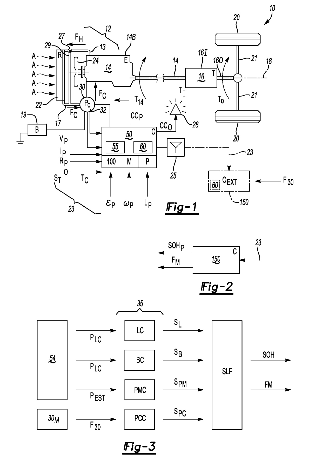
[0018]Referring to the drawings, wherein like reference numbers refer to like components, FIG. 1 provides a schematic view illustration of a vehicle 10 having a thermal management system 12 that is operable for regulating a temperature of a heat source, shown as an example internal combustion engine (E) 14 having an engine block 14B. In operation, the engine 14 provides engine torque (arrow T14) to a transmission (T) 16 arranged on a driveline 18 along with the engine 14, with the engine 14 and transmission 16 coupled to each other via a hydrodynamic torque converter or an input clutch (not shown). An input member 161 of the transmission 16 is thus supplied with an input torque (arrow TI) that may be selectively assisted as needed by an electric motor (not shown) in optional hybrid embodiments. Within the transmission 16, one or more gear sets and additional clutches (not shown) transfer the input torque (arrow TI) to an output member 160 to thereby deliver an output torque (arrow T...


PUM


Abstract

A thermal management system includes an electric coolant pump, power source, and controller. The pump is in fluid communication with a heat source and a radiator, and has pump sensors for determining a pump voltage, speed, and current. The battery energizes the sensors. The controller receives the voltage, speed, and current from the sensors, determines a performance of the pump across multiple operating regions, calculates a numeric state of health (SOH) quantifying degradation severity for each of a plurality of pump characteristics across the regions, and executes a control action when the calculated numeric SOH for any region is less than a calibrated SOH threshold. The pump characteristics include pump circuit, leaking / clogging, bearing, and motor statuses. A vehicle includes an engine or other heat source, a radiator; and the thermal management system. The controller may execute a prognostic method for the electric coolant pump in the vehicle.

Description

INTRODUCTION[0001]Vehicles and other systems may employ an internal combustion engine as a torque-generating device. As internal combustion engines generate intense heat during operation, thermal management techniques are used to maintain engine temperature within a desired temperature range. Cooling of the engine and connected components may be achieved by circulating water, antifreeze, or another suitable coolant to a cylinder head and engine block of the engine where engine heat is extracted. The heated coolant is then fed into and cooled by a radiator assisted by ambient air and a cooling fan before re-entering the engine.[0002]Coolant pumps, colloquially known as water pumps, are the particular pumping devices used to circulate coolant in a closed fluid conduit loop. Inside the pump, rotating impeller blades move the coolant through the pump body and out to the engine. Mechanical coolant pumps are typically driven at engine speed by a rotating belt and engine-driven pulleys. Al...

Claims


Application Information

Patent Timeline
Patent Type & Authority Patents(United States)
IPC IPC(8): F01P5/12F01P5/14F01P7/16F01P11/18
CPCF01P5/12F01P5/14F01P7/164F01P11/18F01P2031/18F01P2005/125F01P2025/32F01P2025/60F01P2031/00F01P7/16F01P5/10F04B51/00
Inventor DUAN, SHIMINGKNIEPER, CHRISTOPHER H.
Owner GM GLOBAL TECH OPERATIONS LLC
Why Eureka
Try Eureka