Optimization-based method and system for localization of flat-panel ultrasonic source with coupled fiber optic sensor

An optical fiber sensor and positioning method technology, which is applied in the measurement of ultrasonic/sonic/infrasonic waves, instruments, and material analysis using sonic emission technology. Linear positioning, improving positioning accuracy, simple and reliable method

Active Publication Date: 2019-05-03
XI AN JIAOTONG UNIV +1
View PDF2 Cites 0 Cited by
  • Summary
  • Abstract
  • Description
  • Claims
  • Application Information

AI Technical Summary

Problems solved by technology

In this way, the peak value of the ultrasonic signal may be shifted by the influence of ultrasonic reflection superposition, mode conversion, etc., which cannot accurately represent the arrival time of the ultrasonic wave, which eventually leads to positioning deviation
And linear positioning with this method usually requires at least two sensors to achieve, which increases the cost
[0005] Traditional piezoelectric ceramic ultrasonic sensors are difficult to apply in narrow spaces and strong electromagnetic environments due to their large size, susceptibility to electromagnetic interference, and inconvenient installation and measurement. Small in weight, light in weight, easy to landfill, and immune to electromagnetic interference, it is more suitable for online monitoring of the working status of remote workpiece equipment
[0006] The fiber optic ultrasonic sensors that have been proposed are mainly interferometric fiber optic sensors, such as (1) Bragg grating, (2) Fabry-Perot cavity, (3) Mach-Zehnder interference, (4) Sagnac interference, These interferometric fiber optic sensors have high cost, high requirements on equipment and complicated sensor manufacturing process, which are not suitable for practical engineering applications.

Method used


Image

  • Optimization-based method and system for localization of flat-panel ultrasonic source with coupled fiber optic sensor
  • Optimization-based method and system for localization of flat-panel ultrasonic source with coupled fiber optic sensor
  • Optimization-based method and system for localization of flat-panel ultrasonic source with coupled fiber optic sensor

Examples


Embodiment Construction

[0041] The present invention will be further described in detail below in conjunction with specific embodiments, which are explanations of the present invention rather than limitations.

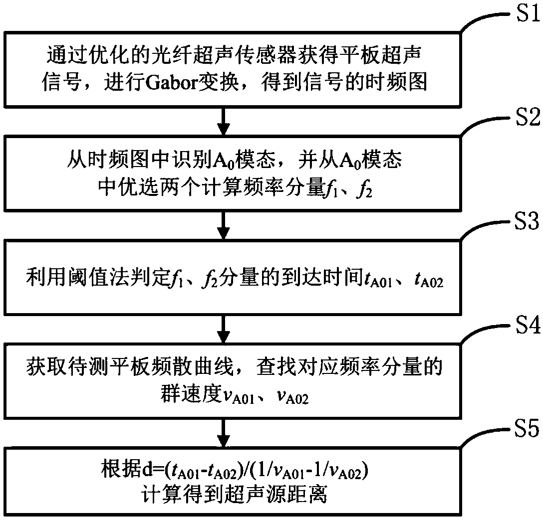
[0042] The present invention is based on an optimized coupled optical fiber sensor flat panel ultrasonic source positioning method, wherein the ultrasonic source is 20kHz-250kHz; as figure 1 As shown, it specifically includes the following steps: (1) Obtain the flat-panel ultrasonic signal through the optimized coupled optical fiber sensor 2, perform Gabor transformation, and obtain the time-frequency diagram of the signal; (2) identify A from the time-frequency diagram 0 modal, and from a 0 Optimal two calculated frequency components f in the mode 1 , f 2 ; (3) Use the threshold method to determine f 1 , f 2 The arrival time of the component t A01 , t A02 ; (4) Obtain the dispersion curve of the plate to be measured, and find the group velocity v of the corresponding frequency componen...


PUM

PropertyMeasurementUnit
thicknessaaaaaaaaaa

Abstract

The invention provides an optimized coupled optical fiber sensor-based flat plate ultrasound source positioning method and system. The system comprises a laser light source, a coupled optical fiber sensor, two photoelectric detectors, a differential amplification circuit and a data collection system, wherein one input end of the coupled optical fiber sensor is connected with the laser light source, two output ends are respectively connected with a first photoelectric detector and a second photoelectric detector, and output ends of the two photoelectric detectors are orderly connected with the differential amplification circuit and the data collection system; the coupled optical fiber sensor comprises an optical fiber acoustic emission sensor, a packaging V-shaped groove and packaging UV adhesive; the coupled optical fiber sensor is formed by subjecting two single mode optical fibers to overcoupling operation, two ends of the single mode optical fibers are packaged in the V-shaped groove via the UV adhesive, and a UV adhesive packaging cut-off part is a sensor coupling region start part. Via use of the method, arrival time and propagation velocity of two frequency components of an A0 mode are extracted, calculated distance of an ultrasound source can be calculated via a flat plate ultrasound signal, and therefore single sensor linear positioning can be realized.

Description

technical field [0001] The invention relates to the field of acoustic emission on-line monitoring, in particular to an optimization-based coupled optical fiber sensor flat panel ultrasonic source positioning method and system. Background technique [0002] In the field of engineering industry, metal sheet is one of the most common engineering components. During its long-term service, it will inevitably be affected by factors such as overload, environment, and human factors, and cracks and other damage will occur, resulting in safety accidents or unnecessary economic loss. In order to prevent such accidents, it is necessary to detect the damage location in a timely and effective manner, and conduct online monitoring of the health status of such plates. [0003] Ultrasound propagates in the form of Lamb waves in the flat plate, and its composition is mainly A 0 with S 0 The two most basic modes, usually S 0 The modal energy is small, and the dispersion effect is not obviou...

Claims


Application Information

Patent Timeline
Patent Type & Authority Patents(China)
IPC IPC(8): G01H9/00G01N29/14
CPCG01H9/004G01N29/14G01N2291/0234G01N2291/0237
Inventor 刘懿莹王霖洁李凤梅赵振宇付文成虞珂
Owner XI AN JIAOTONG UNIV
Why Eureka
Try Eureka