Sphere coating machine

A coating machine and coating technology, applied in the direction of coating, liquid coating device on the surface, etc., can solve the problems of difficult control of depth and time, uneven color of small balls, low coating yield, etc., to achieve guaranteed The effect of coating, uniform specification and uniform quality

Active Publication Date: 2016-08-10
南通梅丽塔智能科技有限公司
View PDF3 Cites 0 Cited by
  • Summary
  • Abstract
  • Description
  • Claims
  • Application Information

AI Technical Summary

Problems solved by technology

[0002] Small balls such as pearls are often inlaid on necklaces, pendants and other jewelry. These small balls are generally made of natural pearls or synthetic resins. In order to make them have the texture and luster of gemstones, the outer surface of the small balls is often coated with Coating, these coatings can not only provide good gloss for the balls, but also play a protective role; the current coating method of the balls is to place the balls on the array plate, so that they are immersed in the coating liquid pan as a whole, The small balls naturally adhere to a layer of coating liquid in the liquid coating tray. Since the small balls are located on the alignment plate, when the small balls are removed, scars will be left on the bottom surface of the contact between the small balls and the alignment plate, which will affect the appearance of the small balls. The coating yield of this type of method is low; in addition, the depth and time of immersion of the ball into the coating solution are not easy to control, which will also make the color of the ball uneven

Method used


Image

  • Sphere coating machine
  • Sphere coating machine

Examples


Embodiment

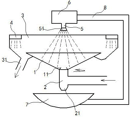
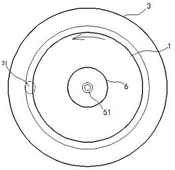
[0015] exist figure 1 , figure 2 In the shown embodiment, this small ball coating machine includes a coating bowl 1, a goal tube 2 and a ball cover 3; the coating bowl 1 is driven by a drive motor, and the coating bowl 1 can The axis rotates; the bowl wall of the coating bowl 1 is made of hard mesh material, and the bowl wall of the coating bowl 1 is made of electric heating wires, and the electric heating wires are electrically connected to the circuit; the goal tube 2 is connected with the bottom of the coating bowl 1 through a bearing, and the coating bowl 1 can rotate freely relative to the goal tube 2; flow ring edge 11; a diversion hole 21 is opened on the goal tube 2, and the diversion hole 21 is located directly below the bottom of the coating bowl 1; the ball collecting cover 3 is sleeved on the coating The outer periphery of the bowl 1, the ball collecting cover 3 is fixed on the body of the small ball coating machine; a ball outlet pipe 31 is installed on the bal...


PUM


Abstract

The invention relates to a sphere coating machine which includes a coating bowl, a sphere inlet pipe and a sphere collecting shield. The coating bowl is driven by a driving motor and can rotate around the axial line itself. A bowl wall of the coating bowl is made of a hard mesh material. The sphere inlet pipe is connected to the bottom of the coating bowl through a bearing. The coating bowl can rotate freely relative to the sphere inlet pipe. The sphere collecting shield sleeves the periphery of the coating bowl and is fixed on a machine body of the sphere coating machine. A sphere outlet pipe is installed in the sphere collecting shield. A cold air ring is installed on the top of the sphere collecting shield. An air outlet of the cold air ring is tangent with the inner wall of the sphere collecting shield. A spray coating pipe is fixedly installed right above the coating bowl. One end of the spray coating pipe is connected to a liquid coating chamber. A sprinkler is arranged on the other end of the spray coating pipe. The sphere coating machine can coating spheres uniformly, is increased in speed of drying the coating, and is effectively increased in coating successful rate of the spheres.

Description

technical field [0001] The invention relates to an automatic coating equipment, in particular, a small ball coating equipment. Background technique [0002] Small balls such as pearls are often inlaid on necklaces, pendants and other jewelry. These small balls are generally made of natural pearls or synthetic resins. In order to make them have the texture and luster of gemstones, the outer surface of the small balls is often coated with Coating, these coatings can not only provide good gloss for the balls, but also play a protective role; the current coating method of the balls is to place the balls on the array plate, so that they are immersed in the coating liquid pan as a whole, The small balls naturally adhere to a layer of coating liquid in the liquid coating tray. Since the small balls are located on the alignment plate, when the small balls are removed, scars will be left on the bottom surface of the contact between the small balls and the alignment plate, which will ...

Claims


Application Information

Patent Timeline
Patent Type & Authority Applications(China)
IPC IPC(8): B05C9/02B05C9/12B05C11/10B05C11/00
CPCB05C9/02B05C9/12B05C11/00B05C11/1039
Inventor 马根昌
Owner 南通梅丽塔智能科技有限公司
Why Eureka
Try Eureka