
Electronic tag packaging equipment

A technology for electronic labels and packaging equipment, which is applied in the direction of circuits, electrical components, and record carriers used by machines. It can solve the problems of high friction of guide rail sliders, affecting the accuracy of chip loading, and high cost, so as to reduce the distance of movement and increase the cost. The effect of operating speed and increasing the rigidity of the system

Pending Publication Date: 2016-08-03
刘宁
View PDF7 Cites 12 Cited by
  • Summary
  • Abstract
  • Description
  • Claims
  • Application Information

AI Technical Summary

Problems solved by technology

Due to the high friction of the guide rail slider of the linear mechanism, the tension control accuracy is not high, which affects the accuracy of film loading to a certain extent
Moreover, traditional institutions are more complicated and costly
[0006] As shown in the publication number CN203825647U, the detection machine used for electronic label detection, the traditional detection reading head and the marking head are respectively driven and controlled by two sets of independent drive mechanisms on the upper and lower sides, that is, four motors are used to realize the detection head respectively. X and Y direction movement, as well as the X and Y direction movement of the marking head, the structure and control are complex and costly

Method used


Image

  • Electronic tag packaging equipment
  • Electronic tag packaging equipment
  • Electronic tag packaging equipment

Examples


Embodiment Construction

[0035] The present invention will be described in detail below with reference to the accompanying drawings, and the features and specific embodiments of the present invention will be clarified.

[0036] figure 1 It is a schematic diagram of the overall structure of the present invention, depicting the positions of various parts on the complete machine equipment.

[0037] The wire film to be produced is output from the feeding part 101 and reaches the flip chip part 102, where the dispensing arm 108 and the bonding arm 109 are respectively responsible for the work of dispensing and bonding. The antenna film with the chip installed is then transported to the heat pressing part 104 through the intermediate tension and deviation correction part 103, and the intermediate tension mechanism 110 is responsible for providing tension and controlling the redundant antenna. The chip and antenna go through a hot pressing process for a few seconds to solidify the glue, fix the chip, and the...


PUM


Abstract

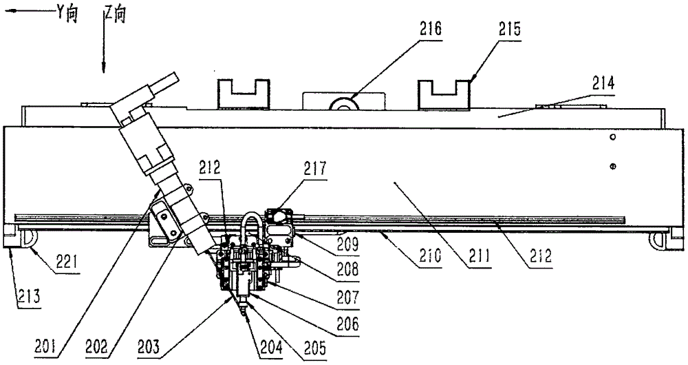
The invention discloses a piece of electronic tag packaging equipment which is used for chip inverted mounting, hot-pressing and production testing of electronic tags. A bonding arm and a dispensing arm are designed into a five-side closed groove structure, and thus a compact and light high-speed bonding arm and dispensing arm structure which is of high rigidity and has a function of flux leakage from the bottom is formed. A bonding head and a corresponding squint-eyed camera lens group are arranged on a linearly-driven carrier, so the antenna photographing task and the bonding or dispensing task are completed in the same position area, and the capacity is improved. By using tension control mechanisms of a linear bearing, a support optical axis, a cylinder and a spring, the friction resistance is reduced, the precision of tension control is improved, and a simple structure and low cost are achieved. A tag test drive mechanism connects a lower detection reading head and an upper marking head through a Y-direction synchronous belt bypassing an antenna film area so as to realize mechanical synchronous movement. The tag test drive mechanism is simplified, and the cost is reduced greatly.

Description

technical field [0001] The invention relates to the field of semiconductor packaging equipment, in particular to a flip-chip electronic label packaging equipment. Background technique [0002] At present, the technology of electronic label packaging equipment, especially the electronic label chip flip packaging equipment is: the film antenna enters the film loader after passing through the feeding tension mechanism and the deviation corrector, and the dispensing camera of the film loader first checks the position of each wire on the film. Take a photo, correct the visual position, and then dispense glue at the exact position. Flip the suction head to remove the chip from the wafer, flip it 180 degrees, and at the same time, the bonding camera will take pictures of the antenna that has been glued. Installed on the corresponding dispensing position. The antenna with the chip installed goes through the intermediate tension mechanism to the heat-pressing unit for a few seconds...

Claims


Application Information

Patent Timeline
IPC IPC(8): H01L21/67G06K19/077G06K7/00
CPCG06K7/00G06K19/077H01L21/67H01L21/67011H01L21/67242H01L21/67294
Inventor 刘宁
Owner 刘宁
Learn More