Brake structure of beam pumping unit
A technology of beam pumping unit and brake disc, which is applied in the direction of brake actuator, gear transmission mechanism, mechanical equipment, etc., can solve the problem that the beam pumping unit cannot be guaranteed to stop working quickly, and the pumping unit cannot stop quickly. Work, large area, etc.
- Summary
- Abstract
- Description
- Claims
- Application Information
AI Technical Summary
Problems solved by technology
Method used
Image
Examples
specific Embodiment 1
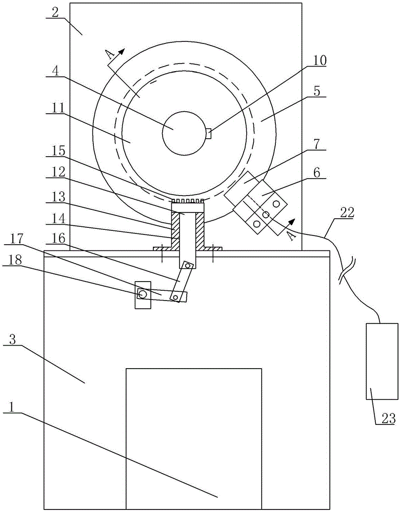
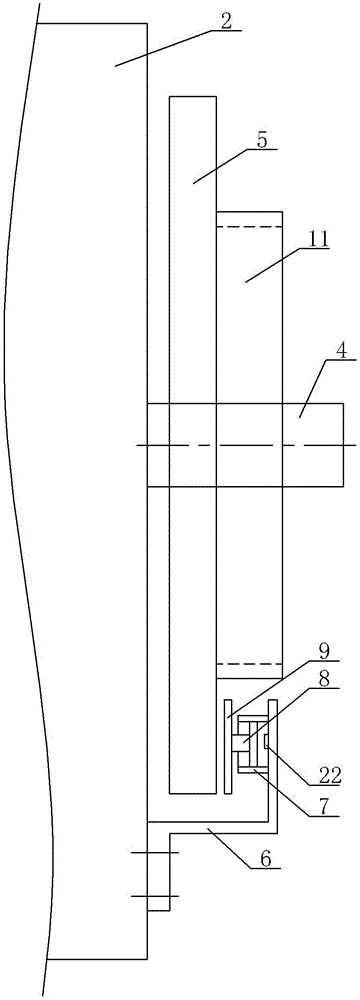
[0023] Specific embodiment one, see Figure 1 ~ Figure 4 : the linear feed part 7 is an oil cylinder structure, the output part 8 is specifically a piston rod, the position of the brake pad support 6 facing the brake disc 5 is fastened with an oil cylinder structure, and the piston rod of the oil cylinder structure is arranged towards the outer end surface of the brake disc 5, A brake pad 9 is fastened on the piston rod, and the braking area of the brake pad 9 is arranged toward the outer end surface of the brake disc 5, and an oil pump structure 23 is externally connected to the cavity of the oil cylinder structure through an oil pipe 22;
specific Embodiment 2
[0024] Specific embodiment two: the linear feed component 7 is an electric cylinder structure, the position of the brake pad support 6 towards the brake disc 5 is fastened with an electric cylinder structure, the piston rod of the electric cylinder structure is arranged towards the outer end surface of the brake disc 5, and the electric cylinder structure is arranged toward the outer end surface of the brake disc 5. The piston rod of the cylinder structure is fastened with a brake pad 9, the braking surface of the brake pad 9 is arranged towards the outer end surface of the brake disc 5, and the electric cylinder is connected to an external power supply through a wire;
specific Embodiment 3
[0025] Specific embodiment three: the linear feed component 7 is a cylinder structure, the position of the brake pad support 6 towards the brake disc 5 is fastened with a cylinder structure, the piston rod of the cylinder structure is arranged towards the outer end surface of the brake disc 5, and the piston of the cylinder structure A brake pad 9 is fastened on the rod, and the braking area of the brake pad 9 is arranged toward the outer end surface of the brake disc 5, and a compressed air source is externally connected to the cavity of the cylinder structure through a gas pipe.
PUM
 Abstract
Description
Claims
Application Information
 - R&D Engineer
- R&D Manager
- IP Professional
- Industry Leading Data Capabilities
- Powerful AI technology
- Patent DNA Extraction
Browse by: Latest US Patents, China's latest patents, Technical Efficacy Thesaurus, Application Domain, Technology Topic, Popular Technical Reports.
© 2024 PatSnap. All rights reserved.Legal|Privacy policy|Modern Slavery Act Transparency Statement|Sitemap|About US| Contact US: help@patsnap.com


