
Acceleration measurement method and device based on particle image velocimetry technology

A particle image velocity measurement and acceleration measurement technology, which is applied in the direction of velocity/acceleration/shock measurement, measuring device, and acceleration measurement, can solve the problems of error sensitivity, particle matching, and particle missing, so as to improve calculation accuracy, maintain physical characteristics, The effect of increasing the amount of information

Active Publication Date: 2016-07-27
BEIHANG UNIV +1
View PDF12 Cites 4 Cited by
  • Summary
  • Abstract
  • Description
  • Claims
  • Application Information

AI Technical Summary

Problems solved by technology

[0003] At present, there are mainly three methods to calculate the acceleration field of the flow field: (1) Calculate by performing Lagrangian tracking (Lagrangian tracking) on ​​the particles on the particle image, but this method often encounters particle matching problems, especially in the case of Particles will be missing during the tracking process of multi-frame particle images; (2) It is calculated by performing Lagrangian pseudo-tracking (Lagrangian pseudo-tracking) on ​​the velocity field, but this method only uses two adjacent instantaneous velocity fields information, the solution accuracy of the acceleration field is limited; (3) it is solved by using the differential scheme on the Euler velocity field, but this method is more sensitive to the error

Method used


Image

  • Acceleration measurement method and device based on particle image velocimetry technology
  • Acceleration measurement method and device based on particle image velocimetry technology
  • Acceleration measurement method and device based on particle image velocimetry technology

Examples


Embodiment 1

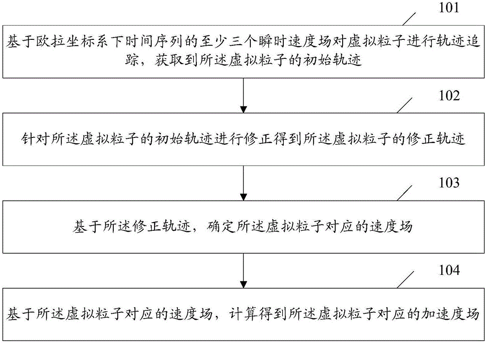
[0027] An embodiment of the present invention provides an acceleration measurement method based on particle image velocimetry technology, such as figure 1 shown, including:

[0028] Step 101: Track the trajectory of the virtual particle based on at least three instantaneous velocity fields in the time series in the Euler coordinate system, and obtain the initial trajectory of the virtual particle;

[0029] Step 102: Correcting the initial trajectory of the virtual particle to obtain the corrected trajectory of the virtual particle; wherein, the corrected trajectory at least includes each coordinate of the virtual particle corresponding to each moment in the time sequence;

[0030] Step 103: Determine the velocity field corresponding to the virtual particle based on the corrected trajectory; wherein, the velocity field includes velocity information corresponding to the virtual particle at each coordinate;

[0031] Step 104: Based on the velocity field corresponding to the virt...

Embodiment 2

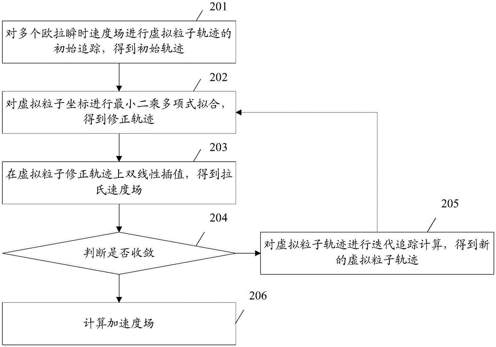
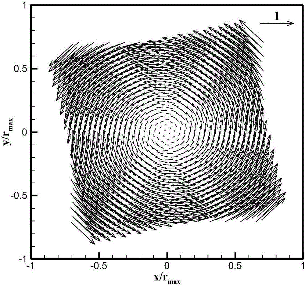
[0085] The method of the present invention will be described below in combination with specific application scenarios. In this embodiment, an artificially generated two-dimensional rigid body rotating flow field is used to simulate the velocity field obtained by the PIV technology as an example for illustration. The number of grid points of the two-dimensional rigid body rotating flow field is 101×101, the time interval between two adjacent frames of velocity fields is Δt=0.01s, and the rotation angular velocity is ω, then the rigid body rotation angle between every two frames of velocity fields is Δθ=ωΔt, Δθ=3° in this application scenario. The number of Euler velocity fields is selected as 5, denoted as V e ={V e (t -2 ), V e (t -1 ), V e (t 0 ), V e (t 1 ), V e (t 2 )}, where t 0 Time is chosen as 0, then t i =i×0.01s, -2≤i≤2. In order to simulate the error produced in PIV velocity measurement, Gaussian white noise whose magnitude is 2% of the average velocity...

Embodiment 3

[0095] The embodiment of the present invention also provides an acceleration measurement device based on particle image velocimetry technology, such as Image 6 As shown, the device can be set inside the computer, including:

[0096] The initial trajectory tracking calculation module 601 is used to track the trajectory of the virtual particle based on at least three instantaneous velocity fields of time series in the Euler coordinate system, and obtain the initial trajectory of the virtual particle;

[0097] The corrected trajectory calculation module 602 is configured to correct the initial trajectory of the virtual particle to obtain the corrected trajectory of the virtual particle; wherein, the corrected trajectory at least includes the virtual particles corresponding to each moment in the time series each coordinate; and based on the corrected trajectory, determine a velocity field corresponding to the virtual particle; wherein, the velocity field includes velocity informa...


PUM


Abstract

The invention discloses an acceleration measurement method and device based on a particle image velocimetry technology.The method comprises the steps that trajectory tracking is conducted on virtual particles based on at least three instantaneous velocity fields of a time sequence of an Eulerian coordinate system, and initial trajectories of the virtual particles are obtained; correction is conducted on the initial trajectories of the virtual particles, and corrected trajectories of the virtual particles are obtained, wherein the corrected trajectories at least comprise coordinates corresponding to the virtual particles at all times in the time sequence;the velocity fields corresponding to the virtual particles are determined based on the corrected trajectories, wherein the velocity fields comprise velocity information corresponding to the virtual particles at all the coordinates; on the basis of the velocity fields corresponding to the virtual particles, acceleration fields corresponding to the virtual particles are obtained through calculation, wherein the acceleration fields comprise acceleration information corresponding to the virtual particles at all the coordinates.

Description

technical field [0001] The present invention relates to particle image velocimetry (PIV, Particle Image Velocimetry) technology in the technical field of laser velocimetry, in particular to an acceleration measurement method and device based on the particle image velocimetry technology. Background technique [0002] PIV technology is a modern laser velocity measurement technology, which is mainly used for flow field velocity measurement, and the flow field velocity field is obtained by tracking the movement of tracer particles in the flow field. PIV technology can realize two-dimensional or three-dimensional velocity field measurement through sheet light source or volume light source, and can also realize time-resolved PIV experimental measurement through high-speed camera imaging, and use the fluid mechanics governing equation, that is, the Navier-Stokes (N-S) equation to reconstruct Flow field pressure field coupled with velocity field. Since the viscous term in the N-S e...

Claims


Application Information

Patent Timeline
IPC IPC(8): G01P15/00
CPCG01P15/00
Inventor 高琪王中一王晋军魏润杰
Owner BEIHANG UNIV
Learn More