Intelligent bearing based on Hall displacement sensor

A displacement sensor, Hall-type technology, applied in the field of bearings, can solve problems such as affecting the accuracy of bearing signals, and achieve the effects of good accuracy, engineering promotion, and easy engineering promotion.

Inactive Publication Date: 2016-07-27
CHANGCHUN INST OF OPTICS FINE MECHANICS & PHYSICS CHINESE ACAD OF SCI
View PDF5 Cites 4 Cited by
  • Summary
  • Abstract
  • Description
  • Claims
  • Application Information

AI Technical Summary

Problems solved by technology

[0003] In order to solve the problem that the accuracy of the bearing signal is affected by the interference signal of the existing intelligent bearing due to the doping of peripheral structural parts, the present invention provides an intelligent bearing based on a Hall-type displacement sensor

Method used


Image

  • Intelligent bearing based on Hall displacement sensor
  • Intelligent bearing based on Hall displacement sensor
  • Intelligent bearing based on Hall displacement sensor

Examples


Embodiment approach 1

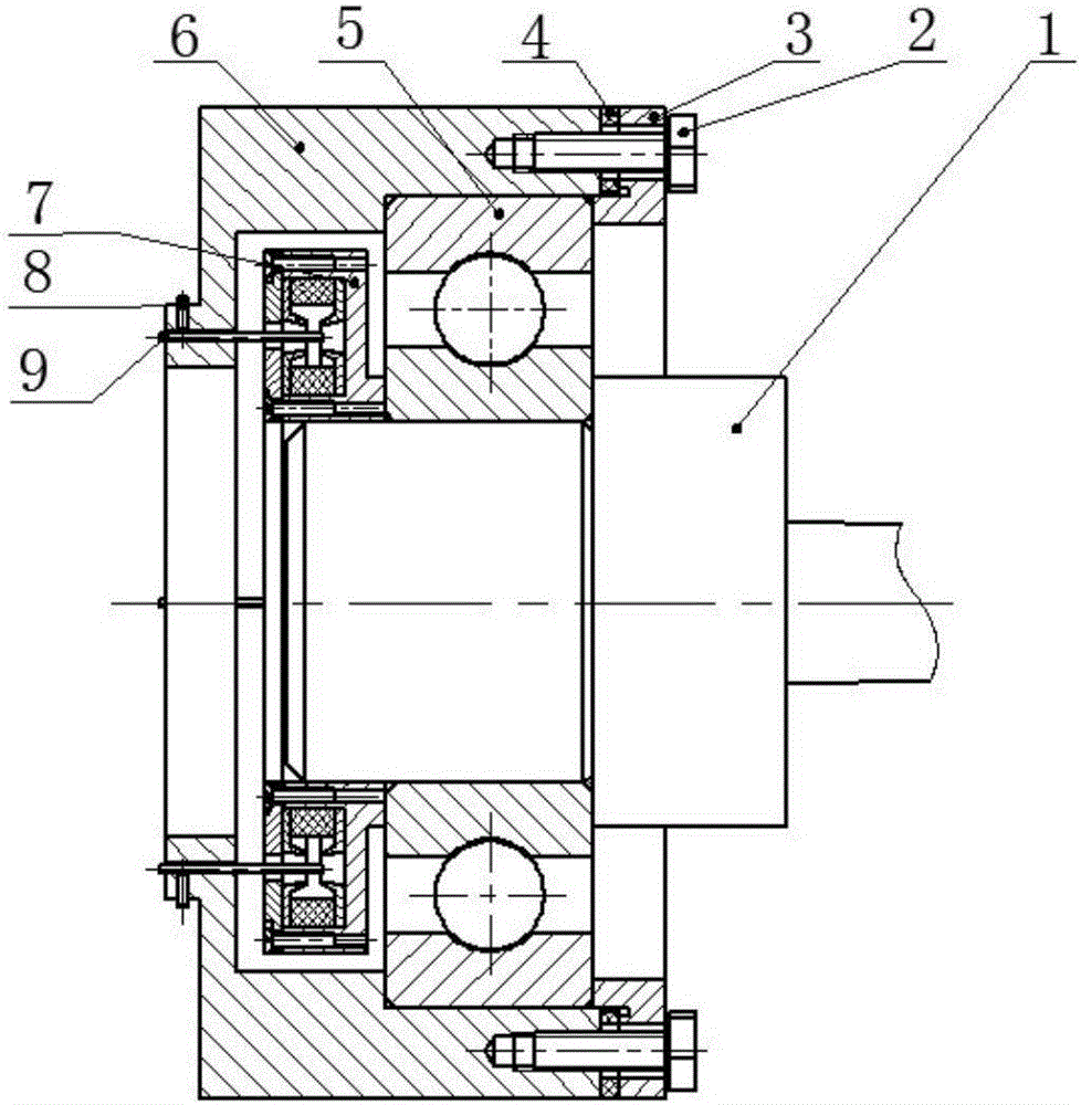
[0024] like figure 1 As shown, the smart bearing based on the Hall-type displacement sensor is mainly composed of a mandrel 1, a bearing end cover 3, a rolling bearing 5, a bearing seat 6, a side-mounted measuring ring 7 and four Hall probes 9.

[0025] The side-mounted measuring ring 7, the rolling bearing 5 and the bearing end cover 3 are arranged coaxially on the bearing seat 6 from the inside to the outside in sequence; the bearing end cover 3 is fixed on the bearing seat 6 by bolts 2, in order to adjust its The size, the gasket 4 is set between the bearing seat 6 and the end cover 3 of the bearing.

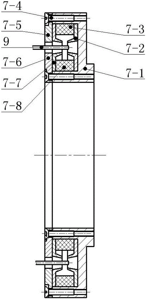
[0026] The four Hall probes 9 are evenly distributed on the ring of the side-mounted measuring collar 7, and are located in the middle of the ring. The rolling bearing 5 and the side-mounted measuring ring 7 are arranged on the outer ring of the mandrel 1, and both of them are evenly fitted with the mandrel 1 for interference or transition fit, and connection methods such as...

Embodiment approach 2

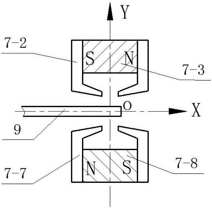
[0030] This embodiment is basically the same as Embodiment 1, the only difference lies in the arrangement of the permanent magnets in the side-mounted measuring ferrule 7 that specifically generate a uniform gradient magnetic field. This embodiment adopts the opposite structure, such as Figure 4 As shown, the polarities of the large magnetic ring 7-3 and the small magnetic ring 7-8 are oppositely placed, and the Hall sensor 9 is placed in the center of the gap generated by the large magnetic ring 7-3 and the small magnetic ring 7-8. This structure will generate a uniform gradient magnetic field in the Y-axis direction, and its magnetic induction intensity is 0 at the center position, and increases linearly along the positive and negative directions of the Y-axis, and the direction is opposite.


PUM


Abstract

The invention provides an intelligent bearing based on a Hall displacement sensor, belongs to the technical field of bearings and aims at solving the problem that the accuracy of bearing signals of an existing intelligent bearing is affected due to the fact that interference signals of peripheral structural parts are involved.The intelligent bearing mainly consists of a mandrel, a bearing end cap, a rolling bearing, a bearing seat, a side-hung measuring ferrule and four Hall probes, wherein the side-hung measuring ferrule, the rolling bearing and the bearing end cap are sequentially and coaxially arranged on the bearing seat from inside to outside, the four Hall probes are evenly distributed on a circular ring of the side-hung measuring ferrule and located at the internal middle position of the circular ring, and the rolling bearing and the side-hung measuring ferrule are arranged on an outer ring of the mandrel.The intelligent bearing integrates non-contact vibration measurement with an intelligent bearing technology, obtains a relative displacement signal of the bearing, isolates the interference signals from the peripheral structural parts of the bearing and improves the signal quality, and engineering application popularization of the intelligent bearing can be easier to achieve compared with existing embedded intelligent bearings.

Description

technical field [0001] The invention relates to an intelligent bearing based on a Hall-type displacement sensor applied to bearing state monitoring, and belongs to the technical field of bearings. technical background [0002] Bearing is one of the key components in the transmission system of mechanical equipment, and its operating status will directly affect the reliability and safety of the system. Effective monitoring of the running state of the bearing is an effective means to avoid catastrophic consequences caused by bearing failure. In order to obtain bearing status signals with high signal-to-noise ratio, smart bearings came into being. The general idea of ​​smart bearings is to integrate sensors as close as possible to the source of the fault, such as the ring or rolling body of the bearing, and then monitor the bearing by analyzing the acquired signals. However, there are still some defects and deficiencies in the existing intelligent bearings. The most prominent ...

Claims


Application Information

Patent Timeline
Patent Type & Authority Applications(China)
IPC IPC(8): G01M13/04G01B7/02F16C33/58F16C35/04
CPCG01M13/04F16C33/581F16C35/04G01B7/02
Inventor 赵海波董吉洪李巍王一建
Owner CHANGCHUN INST OF OPTICS FINE MECHANICS & PHYSICS CHINESE ACAD OF SCI
Why Eureka
Try Eureka