
Robot zero calibration system and method based on laser triangulation ranging

A technology of laser triangulation distance measurement and zero calibration, which is applied in the directions of distance measurement, surveying and navigation, instruments, etc. It can solve the problems of low position and posture measurement accuracy, heavy weight, and difficulty in achieving spatial position measurement accuracy, and achieve calibration The effect of high precision and good versatility

Active Publication Date: 2016-07-27
SHANGHAI JIAO TONG UNIV
View PDF8 Cites 16 Cited by
  • Summary
  • Abstract
  • Description
  • Claims
  • Application Information

AI Technical Summary

Problems solved by technology

[0005] (1) Low accuracy of position and orientation measurement: Whether it is the binocular stereo vision calibration method or the laser tracker method, it is necessary to install corresponding measurement components at the end of the robot, and cooperate with certain regular motion control and methods
Therefore, it is difficult to achieve high spatial position measurement accuracy;
[0006] (2) Large volume and heavy weight: the existing calibration methods are basically based on laser and vision, all of which are assembled from separate components (camera, lens, mirror, laser, etc.) to form a calibration system, which has a large volume and heavy weight. question;
[0007] (3) It has an impact on the performance of the robot body: due to the addition of additional measuring devices and components at the end of the robot, the positive and negative solutions of the robot motion model will change slightly, which is not conducive to the application of the robot

Method used


Image

  • Robot zero calibration system and method based on laser triangulation ranging
  • Robot zero calibration system and method based on laser triangulation ranging
  • Robot zero calibration system and method based on laser triangulation ranging

Examples


Embodiment Construction

[0037] The present invention will be described in detail below in conjunction with specific embodiments. The following examples will help those skilled in the art to further understand the present invention, but do not limit the present invention in any form. It should be pointed out that for those of ordinary skill in the art, a number of modifications and improvements can be made without departing from the concept of the present invention. These all belong to the protection scope of the present invention.

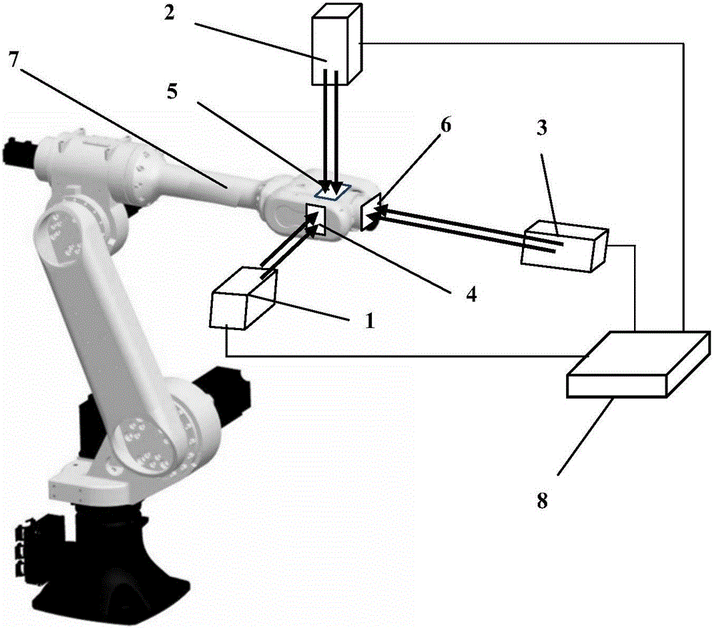
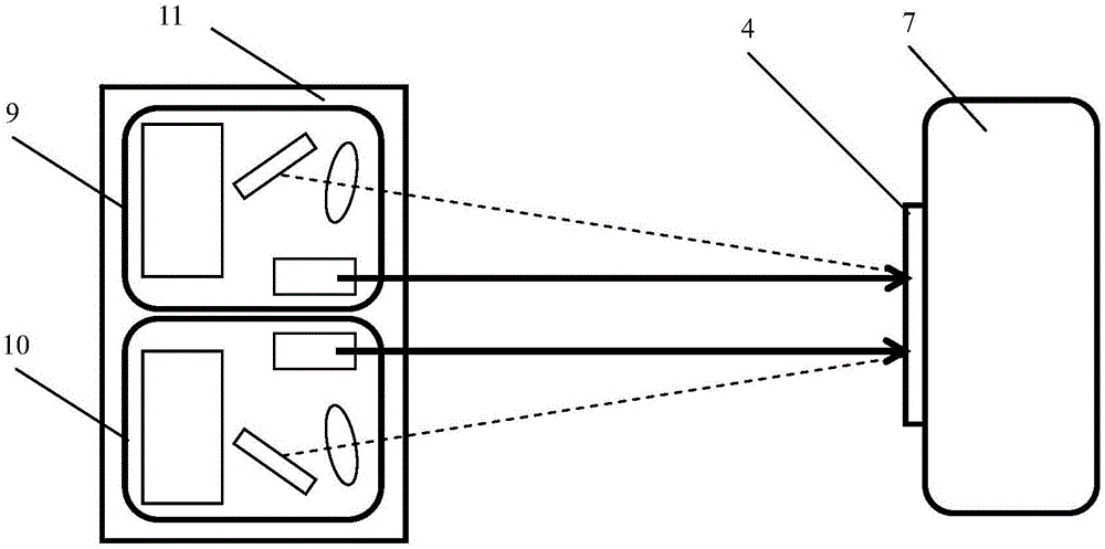
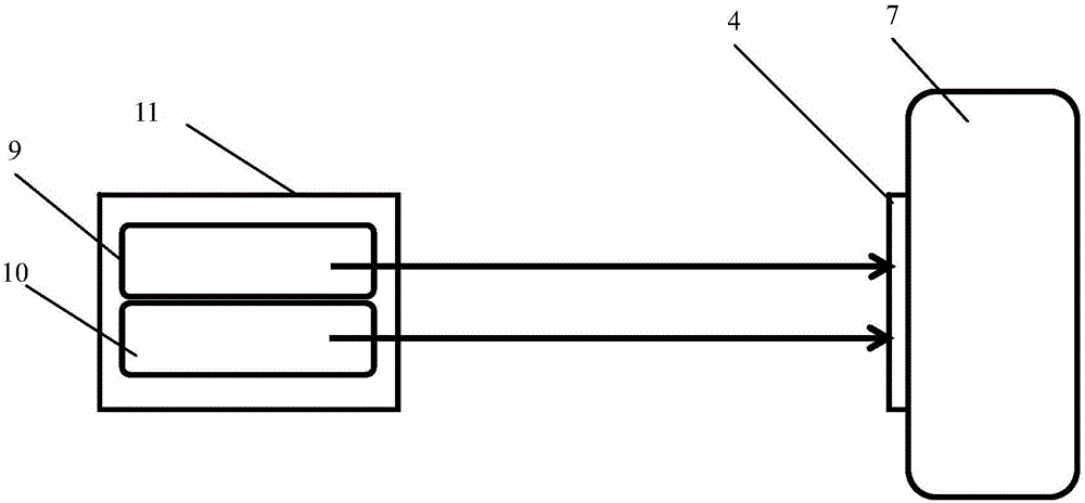
[0038] Such as figure 1 As shown, a robot zero calibration system based on laser triangulation distance measurement consists of a first calibrator 1, a first calibrator 2, a first calibrator 3, a first target 4, a second target 5, and a third target 6. , And a controller 8, wherein: the first calibrator 1, the first calibrator 2, the first calibrator 3 are respectively arranged on a rigid base at any position around the robot body 7 environment; the first target 4, the firs...


PUM


Abstract

The invention discloses a robot zero calibration system and method based on laser triangulation ranging. The system comprises calibrators, targets and a controller. The three calibrators are installed on rigid bases at any position in the surroundings of a robot respectively, the three targets are correspondingly pasted on three perpendicular planes, corresponding to the calibrators, of the tail end of a robot body, and the controller is arranged at a certain surrounding position needed by the robot. Each calibrator is composed of two laser triangulation displacement sensors with the absolute displacement measurement function and a shell, wherein read data of the two laser triangulation displacement sensors is directly transmitted to the controller, and the controller achieves zero calibration of the robot through data processing. The robot zero calibration system and method are high in calibration precision, free of influences on the robot body and suitable for design of novel robots and accessory installation of in-service robots and have the highest universality.

Description

Technical field [0001] The invention relates to a robot zero position calibration system and method, in particular to a robot zero position calibration system and method based on laser triangulation ranging. Background technique [0002] The robot is an open-loop kinematics structure. The angle value of the joint rotation is obtained through an angle measuring device (usually an incremental encoder), and the spatial pose of the current robot end effector is obtained through the robot kinematics model. Because in the robot production process, mechanical manufacturing and assembly, encoder, motion control and other links inevitably have various errors, gravity deformation, thermal deformation, clearance and wear, and other random errors during the use of the robot, so Compared with the ideal value, the actual space pose of the robot end usually has a large deviation, which affects the robot's motion accuracy. [0003] By calibrating the robot to obtain the accurate structure and pos...

Claims


Application Information

Patent Timeline
IPC IPC(8): G01C3/10G01C25/00
CPCG01C3/10G01C25/00
Inventor 陶卫赵辉高强肖素枝张正琦杨红伟邓凯鹏赵思维尹小恰田家田高文俊李坤
Owner SHANGHAI JIAO TONG UNIV
Learn More