Tool for controlling side perpendicularity of small prisms on disc

A technology for controlling sides and prisms, applied in manufacturing tools, workpiece clamping devices, etc., can solve problems such as long turnaround time, high scrap rate, and product accuracy that cannot meet the requirements of drawings, so as to reduce production costs, reduce scrap rate, The effect of shortening the production cycle

Active Publication Date: 2016-07-27
JIANGSU PRECISE WAY OPTICS CO LTD
View PDF7 Cites 6 Cited by
  • Summary
  • Abstract
  • Description
  • Claims
  • Application Information

AI Technical Summary

Problems solved by technology

[0008] Aiming at the problems existing in the prior art that there is no suitable tooling when controlling the side sagging of the small prism upper plate, the product precision cannot meet the drawing requirements, the scrap rate is high, and the turnaround time is long. The present invention provides a small prism upper plate control side hanging work clothes

Method used


Image

  • Tool for controlling side perpendicularity of small prisms on disc
  • Tool for controlling side perpendicularity of small prisms on disc

Examples


Embodiment 1

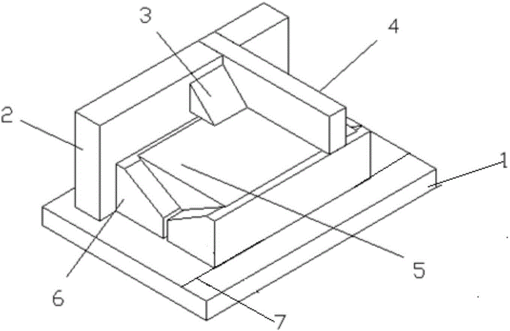
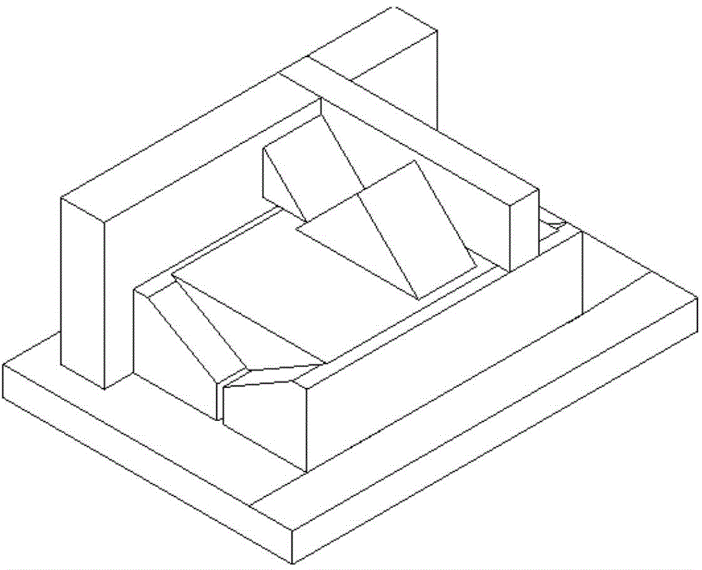
[0035] like figure 1As shown, a small prism upper plate control side sagging frock of this embodiment includes a base 1, a horizontal positioning block 2, a stopper 4 and a horizontal support body 5, and also includes a V-shaped limit block 6, a limit block 3 and positioning marking line 7, wherein base 1, horizontal positioning block 2, block 4, limiting block 3, horizontal body 5 and V-shaped limiting block 6 are made of colorless optical glass; the V-shaped limiting The block 6 is a V-shaped groove structure with an opening angle of 90°, the specification is 160*120*40mm, the tolerance is ±0.01mm, the right angle accuracy is ±30", and one side of the bottom surface extends the positioning mark line 7 and the base 1 Glue and fix the connection with optical glue, one of the rectangular sides is closely attached to the horizontal positioning block 2, and is lower than the height of the wide surface of the horizontal positioning block 2, ensuring that the sagittal height of the...

Embodiment 2

[0044] The specific structure of a small prism upper plate control side sagging frock of this embodiment is basically the same as that of embodiment 1, the difference is that it also includes a spirit level; The V-shaped groove structure uses local materials and does not need to make special limit blocks, which reduces the production cost.

[0045] In this embodiment, a small prism upper plate controls the side sag, and the basic usage steps are the same as those in Embodiment 1, the difference is that the entire tooling is calibrated with a spirit level before pasting the small prism.


PUM


Abstract

The invention discloses a tool for controlling side perpendicularity of small prisms on a disc and belongs to the field of optical component assembling techniques. The tool for controlling side perpendicularity of the small prisms on the disc comprises a base, a horizontal positioning block, a check block and a horizontal support and is characterized by further comprising a V-shaped limiting block, wherein the V-shaped limiting block is of a V-shaped groove structure with a 90-degree opening angle; the base is of a square platy structure; the horizontal positioning block is of a cuboid block structure and is provided with a square groove; the notch of the groove faces upward, is formed in the upper surface of the base in a vertically inverted mode and is close to the sideline of the base; the check block is also of a cuboid block structure; one end of the check block is embedded in the groove of the horizontal positioning block in a matched mode, and the other end of the check block is arranged at the V-shaped notch of the V-shaped limiting block in a vertically inverted mode; the horizontal support is of a right-angle triangle body structure and is arranged in the 90-degree V-shaped groove of the V-shaped limiting block in a matched mode. Through the tool, the purposes of controlling the side perpendicularity of small prism products with small dimensional tolerance on the disc, reducing the rejection rate and improving the working efficiency can be achieved.

Description

technical field [0001] The invention relates to the technical field of optical component assembly, in particular to a tooling for controlling side sag on a small prism upper plate. Background technique [0002] How to ensure the angular accuracy of the prism in the mass production process is a core problem that must be solved in every process technology solution. Because each process in the manufacturing process may affect the angular accuracy, the control of the angular accuracy runs through the entire manufacturing process, and it also requires a solution to the influencing factors of each process. If this problem cannot be solved well, even with the most advanced processing equipment, a large number of reworked products will be caused due to the out-of-tolerance angle, which will increase the workload and cannot fully reflect the characteristics of efficient production. [0003] At present, in the production process of small prisms (generally referring to products with s...

Claims


Application Information

Patent Timeline
IPC IPC(8): B25B11/00
CPCB25B11/00
Inventor 马成
Owner JIANGSU PRECISE WAY OPTICS CO LTD
Why Eureka
Try Eureka