Attachment milling head spindle positioning structure

A technology of positioning structure and milling head, which is applied in the direction of milling machine equipment, milling machine equipment details, metal processing equipment, etc., can solve the problems of time-consuming and labor-intensive, and achieve the effect of low cost, simple operation and reasonable structure

Active Publication Date: 2018-02-06
WUHAN HEAVY MACHINE TOOL GRP
View PDF8 Cites 0 Cited by
  • Summary
  • Abstract
  • Description
  • Claims
  • Application Information

AI Technical Summary

Problems solved by technology

However, every time the accessory milling head is installed, it is necessary to manually observe whether the machine tool spindle and the accessory spindle are connected normally, and to make appropriate adjustments to the accessory spindle, which is time-consuming and labor-intensive every time.

Method used


Image

  • Attachment milling head spindle positioning structure
  • Attachment milling head spindle positioning structure

Examples


Embodiment Construction

[0014] Below in conjunction with specific embodiment, further illustrate the present invention. It should be understood that this embodiment is only used to illustrate the present invention and is not intended to limit the scope of the present invention. In addition, it should be understood that after reading the content of the present invention, those skilled in the art can make various changes or modifications to the present invention, and these equivalent forms also fall within the scope defined by the appended claims of the present application.

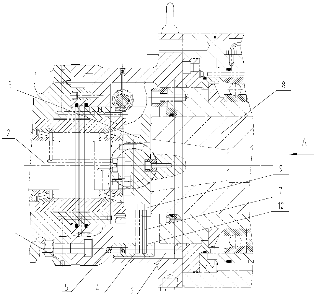
[0015] as attached figure 1 As shown, the attachment main shaft positioning structure includes a transition housing 1, the transition housing 1 is placed horizontally, and the attachment main shaft 2, positioning dial 3, and positioning key block 4 are arranged on the transition housing 1; the positioning dial 3 and the attachment The main shaft 2 is connected and can drive the accessory main shaft 2 to rotate; the positioning di...


PUM


Abstract

The invention relates to a main shaft positioning structure of an accessory milling head, comprising a transition housing, a main shaft of an accessory milling head, a positioning dial, a positioning key block, a pressure spring, a small transverse shaft and a positioning pin. The accessory milling head spindle is installed in the transition housing, the positioning dial is connected with the accessory milling head spindle, which can drive the accessory milling head spindle to rotate, one end of the positioning pin is inserted into the keyway opened on the positioning dial, and the other end is fixed on the small horizontal shaft On; the small horizontal shaft and the pressure spring are placed in the positioning key block. The invention has a simple structure, can ensure the normal docking of the main shaft of the machine tool and the main shaft of the accessory without manual observation and adjustment, improves the working efficiency when the milling head of the accessory is mounted, and provides a basis for automatic replacement of the accessory.

Description

[0001] Field [0002] The invention relates to a spindle positioning structure of an accessory milling head of a large mechanical processing equipment, in particular to a spindle positioning structure of an accessory milling head of a large horizontal numerical control boring and milling machine. Background technique [0003] With the rapid development of processing and manufacturing industry, domestic related manufacturers have higher and higher requirements for processing machine tools. In addition to strong milling, boring, drilling and other functions, the floor milling and boring machine is equipped with high-precision CNC Functional accessories such as rotary table and milling head can complete the processing of five surfaces at one time, which can greatly improve production efficiency. Therefore, each machine tool is more or less equipped with several accessory milling heads to meet various processing parts. requirements. However, every time the accessory milling head ...

Claims


Application Information

Patent Timeline
Patent Type & Authority Patents(China)
IPC IPC(8): B23C9/00B23B19/02
Inventor 桂林李嵘周伟吴海强稽仲萍
Owner WUHAN HEAVY MACHINE TOOL GRP
Why Eureka
Try Eureka