Vehicle-mounted charging system and vehicle

A vehicle-mounted charging and vehicle-mounted technology, applied in vehicle components, vehicle energy storage, current collectors, etc., can solve the problems of low power, unreusable circuit devices, and limited mileage of power batteries, etc., to achieve flexible charging methods and satisfy users effect of demand

Inactive Publication Date: 2016-07-20
BYD CO LTD
View PDF3 Cites 13 Cited by
  • Summary
  • Abstract
  • Description
  • Claims
  • Application Information

AI Technical Summary

Problems solved by technology

However, the cruising range of electric vehicles is limited by the power battery, how to conveniently charge the power battery is a problem that many electric vehicles need to solve
For now, there are mainly two charging methods for electric vehicles, off-board and on-board. However, the off-board method has high construction costs and covers a wide area, and cannot meet the needs of users for self-charging; most of the on-board methods are single-phase AC chargers. Moreover, circuit devices cannot be reused, so it is a current research direction to develop a charging system that is compatible with various charging devices and external power supplies and has a high degree of integration.
[0003] Most electric vehicles only use external commercial or household single-phase AC power charging, or can only use DC power charging at electric vehicle charging stations, and cannot achieve DC / single-phase charging mode compatibility
In addition, the existing vehicle-mounted inverter power supply generally starts from the low-voltage battery to invert the output, the power is small, and the circuit components cannot be reused.

Method used


Image

  • Vehicle-mounted charging system and vehicle
  • Vehicle-mounted charging system and vehicle
  • Vehicle-mounted charging system and vehicle

Examples


Embodiment Construction

[0013] Embodiments of the present invention are described in detail below, examples of which are shown in the drawings, wherein the same or similar reference numerals designate the same or similar elements or elements having the same or similar functions throughout. The embodiments described below by referring to the figures are exemplary and are intended to explain the present invention and should not be construed as limiting the present invention.

[0014] The on-board charging system and the vehicle according to the embodiments of the present invention will be described below with reference to the accompanying drawings.

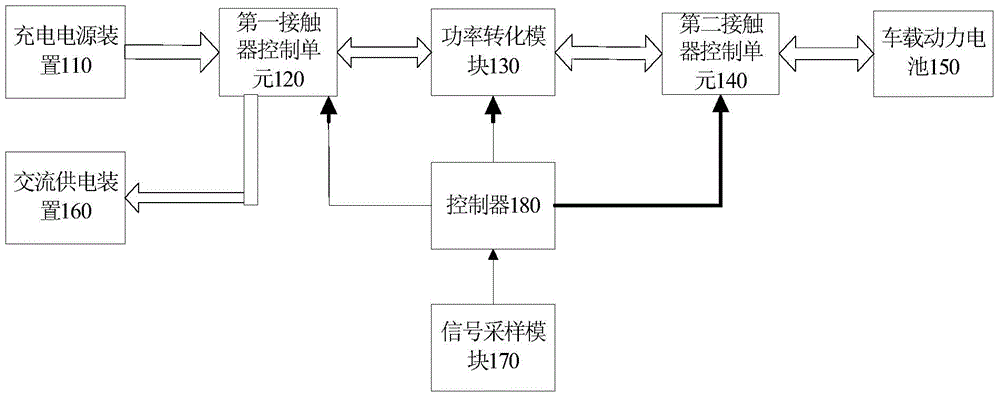
[0015] figure 1 is a structural block diagram of an on-board charging system according to an embodiment of the present invention. Such as figure 1 As shown, the vehicle charging system according to an embodiment of the present invention includes: a charging power supply device 110, a first contactor control unit 120, a power conversion module 130, a seco...


PUM


Abstract

The invention discloses a vehicle-mounted charging system. The vehicle-mounted charging system comprises a charging power supply device, a power conversion module, a second contactor control unit, a vehicle-mounted power battery, an AC power supply device and a controller, wherein the charging power supply device is used for outputting a first alternating current or a first direct current, the power conversion module is used for converting the first alternating current or the first direct current to a second direct current in a charging mode so as to charge the vehicle-mounted power battery, and converting a third direct current output from the vehicle-mounted power battery to a second alternating current in an inversion mode, the AC power supply device is used for triggering an inversion signal when an AC load is accessed and supplying power to the AC load with the second alternating current, and the controller is used for controlling the power conversion module to enter the charging mode so as to achieve charging when a charging signal is received, and controlling the power conversion module to enter an inversion mode so as to achieve discharging when the inversion signal is received. The vehicle-mounted charging system according to the embodiment of the invention has functions of charging and discharging and is flexible in the charging mode, and the user demand is met. The invention also discloses a vehicle.

Description

technical field [0001] The invention relates to the technical field of automobiles, in particular to an on-vehicle charging system and a vehicle. Background technique [0002] With the increasing shortage of energy and the increasingly severe environmental pollution, energy-saving and environmentally friendly electric vehicles have received more and more attention. However, the cruising range of electric vehicles is limited by the power battery. How to conveniently charge the power battery is a problem that many electric vehicles need to solve. For now, there are mainly two charging methods for electric vehicles, off-board and on-board. However, the off-board method has high construction costs and covers a wide area, and cannot meet the needs of users for self-charging; most of the on-board methods are single-phase AC chargers. Moreover, circuit devices cannot be reused, so it is a current research direction to develop a charging system that is compatible with various charg...

Claims


Application Information

Patent Timeline
Patent Type & Authority Applications(China)
IPC IPC(8): H02J7/00H02J7/10B60L11/18
CPCY02T10/70
Inventor 滕景翠邓林旺
Owner BYD CO LTD
Why Eureka
Try Eureka