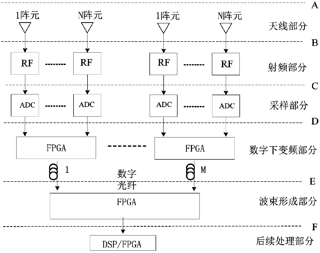
A digital array receiving channel performance automatic test system based on cpci

An automatic test system and receiving channel technology, applied in the field of digital array radar, can solve the problems of cumbersome test work and few test indicators, etc.

Active Publication Date: 2019-04-05
UNIV OF ELECTRONICS SCI & TECH OF CHINA
View PDF4 Cites 0 Cited by
  • Summary
  • Abstract
  • Description
  • Claims
  • Application Information

AI Technical Summary

Problems solved by technology

[0004] At present, traditional instrument-based test systems, such as network analyzers, signal sources with oscilloscopes and spectrum analyzers, often can only test the previous part of the digital receiving part of the receiving channel of the array radar, and the test work is cumbersome; while other digital Receivers, with fewer test indicators, are often only used for performance testing of digital receivers

Method used


Image

  • A digital array receiving channel performance automatic test system based on cpci
  • A digital array receiving channel performance automatic test system based on cpci
  • A digital array receiving channel performance automatic test system based on cpci

Examples


Embodiment Construction

[0014] In order to make the purpose, technical solution and advantages of the present invention clearer, the present invention will be further described in detail below in conjunction with the implementation methods and accompanying drawings.

[0015] see figure 2 , 3 , the automatic test system of the present invention includes a host computer, a multi-channel intermediate frequency data acquisition board (also called a test board) based on a cPCI interface. The hardware acquisition part of the array radar digital receiver test system based on cPCI interface mainly includes FPGA chip (and its configuration chip), multiple DDR2 chips (two or more), cPCI interface chip, and multiple photoelectric conversion modules. A photoelectric conversion unit composed of multiple optical modules (single-mode or multi-mode), used to convert the optical signals input by optical fibers 1 to N into high-speed serial signals, which are connected to the high-speed serial interface of the FPGA ...


PUM


Abstract

The invention discloses a cPCI-based digital array radar receiving channel performance automatic test system, which includes a host computer, a data acquisition board based on a cPCI interface, and the data acquisition board includes a cPCI interface unit, a processing control unit, a cache unit, a photoelectric The conversion unit, wherein the photoelectric conversion unit is connected to the processing control unit, the processing control unit collects data through the photoelectric conversion unit and stores it in the cache unit, the processing control unit communicates with the host computer through the cPCI interface unit, and the processing control unit is based on the control instructions of the host computer Configure working parameters and transmit cached data to the host computer; the host computer is used to issue control instructions to the data acquisition board to perform data acquisition, draw the received data as frequency domain and / or time domain waveforms and output them, and perform tests based on the received data Index operation and output. The invention is used for the performance test of each receiving part of the digital array radar, and can perform fast, efficient and accurate performance evaluation and fault location.

Description

technical field [0001] The invention belongs to the digital array radar technology, in particular to an automatic test technology for the performance of the receiving channel of the digital array radar. Background technique [0002] Digital array radar adopts a large number of digital technologies when transmitting and receiving, which is easy to achieve low sidelobe and adaptive anti-jamming by amplitude and phase weighting. It is easy to control beam pointing through digital delay and digital phase shifting, and realize multi-beam multi-target processing and wide bandwidth angle. functions such as scanning. [0003] The performance of single receiving channel and multiple channels of digital array radar will directly affect the radar's search for targets, tracking accuracy, imaging effect and so on. Therefore, in the debugging process before the assembly of the radar machine, it is necessary to measure the performance indicators of each receiving sub-component. The recei...

Claims


Application Information

Patent Timeline
Patent Type & Authority Patents(China)
IPC IPC(8): G01S7/40
CPCG01S7/40
Inventor 严济鸿杨昉但誉风马玉卿何子述
Owner UNIV OF ELECTRONICS SCI & TECH OF CHINA
Why Eureka
Try Eureka