
Tunnel supporting drilling robot

A robot and tunnel technology, which is applied in the direction of reciprocating drilling rigs, drilling equipment and methods, drilling equipment, etc., can solve the problems of complex design, inflexible drilling, and low control accuracy, and achieve high positioning accuracy, small footprint, Flexible drilling effect

Active Publication Date: 2016-07-20
HARBIN ENG UNIV
View PDF14 Cites 6 Cited by
  • Summary
  • Abstract
  • Description
  • Claims
  • Application Information

AI Technical Summary

Problems solved by technology

However, it is difficult to ensure that the drilling axis of this structure passes through the center of the tunnel. The platform is adjusted by multiple electric cylinders, and the control accuracy is not high.
The patent application number CN201120173378.3 is called "Tunnel Top Drilling Machine". It consists of an anti-derailment track flatbed, a herringbone frame, a drilling support platform and a generator. Punching, can not achieve any position of punching
These patent documents can realize drilling, but the structural form and positioning driving method are different. The positioning of the above-mentioned devices is either very complicated in design, or the drilling is not flexible enough.

Method used


Image

  • Tunnel supporting drilling robot
  • Tunnel supporting drilling robot
  • Tunnel supporting drilling robot

Examples


Embodiment Construction

[0014] The present invention will be further described in detail below in conjunction with the accompanying drawings and specific embodiments.

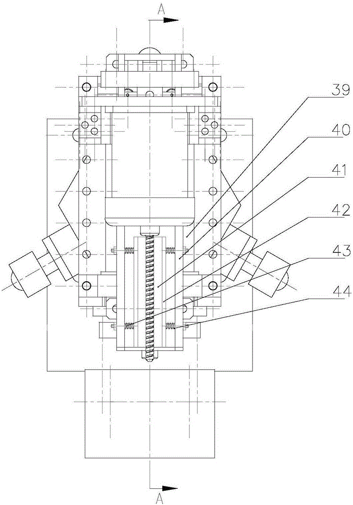
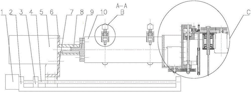
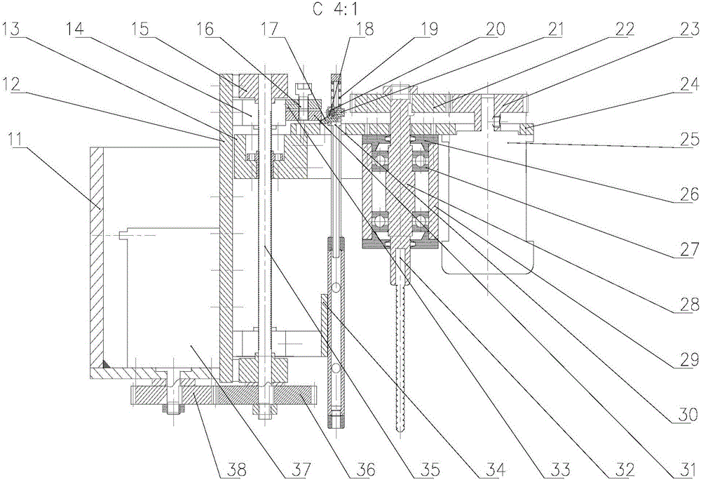
[0015] combine Figure 1 to Figure 6 , The main structure of the tunnel support drilling robot includes 1. Axial traveling motor, 2. Large sliding table, 3. Fixed slider, 4. Axial traveling screw, 5. Circumferential rotating motor, 6. Rotating motor connection Plate, 7, large slide, 8, coupling, 9, flange, 10, hexagonal shaft, 11, radial feed motor connection plate, 12, small slide, 13, small slide, 14, shaft seat , 15, lead screw bearing seat, 16, anchor rod push rod elastic fine-tuning bolt, 17, wedge block, 18, wedge block fixing plate, 19, spring, 20, wedge block spring, 21, guide cylinder rod, 22, drilling Transmission gear, 23, drilling transmission pinion, 24, connecting plate, 25, drill bit motor, 26, bearing cover, 27, bearing, 28, shaft, 29, cylinder, 30, anchor rod push rod, 31, moving Block, 32, drill bit, 33, fixed bloc...


PUM


Abstract

The invention provides a tunnel supporting drilling robot which comprises a brushless direct current motor for the power source of a drill bit, a gear reducer, a support structure of an overall tunnel supporting robot, namely an improved universal bullseye wheel, a screw sliding table, a rotary motor, a coupler, a photoelectric coded disk feedback system, an electric cabinet and an automatic ejection mechanism, wherein a miniature screw sliding table is adopted for feeding of a drilling device; the power of the screw sliding table is a stepper motor; the screw sliding table is positioned and driven along the axial direction of a tunnel; the rotary motor is positioned along the periphery of the tunnel; the photoelectric coded disk feedback system is used for achieving accurate positioning; the electric cabinet is arranged at the tail part of the overall robot; the automatic ejection mechanism of a wedge block anchor rod is especially designed for achieving automatic insertion of the anchor rod; and various parts are tightly matched to form the tunnel supporting robot. A tunnel supporting drilling structure employing improved universal bullseye wheels arranged at three angles of 120 degrees along the circumference direction of the tunnel is utilized; position close-loop control is adopted; and charged self locking of a stepping driver is utilized, so that the positioning accuracy is high; the structure is simple; and drilling is flexible.

Description

technical field [0001] The invention relates to a drilling robot, in particular to a tunnel support drilling robot. Background technique [0002] Usually tunnel robots are mostly inspection robots. Domestic tunnel rock drilling mostly uses air guns, which have relatively large drilling diameters, high heat generation, and high power consumption. They are still manually controlled on site, and the labor intensity is relatively high. Foreign countries started earlier in this area and achieved more results. From the development of the first practical hydraulic rock drilling machine in France to the development of an automatically controlled tunnel rock drilling rig by a Norwegian company, the precision and automation of rock drilling have been further improved. However, there are not many studies on the mechanism of rockburst through tunnel support drilling robots, and further verification and research are needed based on actual conditions. Central South University has conduc...

Claims


Application Information

Patent Timeline
Patent Type & Authority Applications(China)
IPC IPC(8): E21B15/00E21B1/00
CPCE21B1/00E21B15/00
Inventor 张忠林洪维周辉朱勇周雪鹏李思宇田鹏
Owner HARBIN ENG UNIV
Learn More