
Circuitous water discharging structure of combined type door and window

A water outlet structure and combined technology, applied in the direction of condensate water discharge, wing fan arrangement, insect control, etc., can solve the problems of slow water outlet, difficult water outlet, entry of mosquitoes and flies, etc. Effect

Inactive Publication Date: 2016-07-20
张祯翔
View PDF6 Cites 0 Cited by
  • Summary
  • Abstract
  • Description
  • Claims
  • Application Information

AI Technical Summary

Problems solved by technology

[0002] At present, the combined doors and windows used in building houses have problems such as slow water discharge, difficult water discharge, and mosquitoes and flies entering the water outlet holes.

Method used


Image

  • Circuitous water discharging structure of combined type door and window
  • Circuitous water discharging structure of combined type door and window
  • Circuitous water discharging structure of combined type door and window

Examples


Embodiment

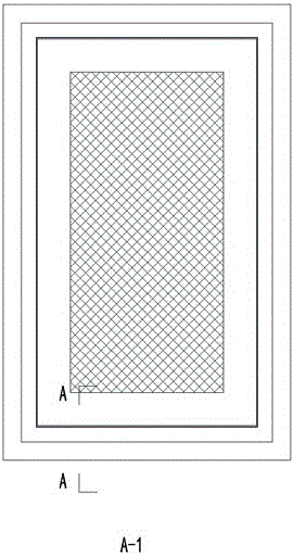
[0020] Embodiment: A combined door and window detour water outlet structure

[0021] like figure 1 , figure 2 , image 3 , Figure 4 , Figure 5 shown.

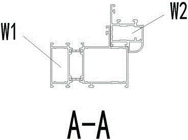
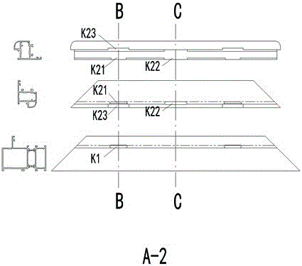
[0022] Step 1: Sawn the inward-opening and inverting window frame W1 that needs to be punched out of the water hole, and punch out the water outlet K1 according to the requirements and position on the punching machine.

[0023] Step 2: Sawn the casement protective screen window frame W2 that needs to be milled out of the water hole, and mill out the similar size on the milling machine according to the required size. image 3 The water outlet holes K21, K22, K23.

[0024] Step 3: Install all materials according to the requirements of the combined window.


PUM


Abstract

The invention provides a circuitous water discharging structure of combined type door and window. The circuitous water outlet structure is beautiful in appearance, and the problems that a common rain shielding cover falls off so that water discharging is influenced, mosquitoes and flies enter and the like are also solved.

Description

technical field [0001] The invention relates to a combined door and window used in building houses, and belongs to the technical field of building house window products. Background technique [0002] The combined doors and windows currently used in building houses have problems such as slow water outlet, difficult water outlet, and mosquitoes and flies entering the water outlet hole. Contents of the invention [0003] The invention provides a combined door and window circuitous water outlet structure, which not only has a beautiful appearance, but also solves the problems of difficult water outlet and entry of mosquitoes and flies. [0004] Technical scheme of the present invention is: [0005] The combined door and window circuitous water outlet structure allows rainwater to be discharged through the water outlet holes of the inward-opening and inward-turning windows and the water outlet holes of the flat-open protective screen window, and the circuitous light-shielding ...

Claims


Application Information

Patent Timeline
Patent Type & Authority Applications(China)
IPC IPC(8): E06B7/14E06B3/50E06B9/52
CPCE06B7/14E06B3/50E06B9/52
Inventor 不公告发明人
Owner 张祯翔
Learn More