
Textile printing and dyeing device

A technology for textile printing and dyeing and fabrics, which is applied to the field of textile printing and dyeing devices, can solve the problems of dye passing through the thread, easy to be electrostatically adsorbed, uneven printing and dyeing, etc., and achieve the effects of preventing uneven printing and dyeing, avoiding dye precipitation, and improving printing and dyeing quality.

Inactive Publication Date: 2016-07-20
CHANGSHU SHUNWANG NETWORK TECH SERVICE CO LTD
View PDF0 Cites 5 Cited by
  • Summary
  • Abstract
  • Description
  • Claims
  • Application Information

AI Technical Summary

Problems solved by technology

Regardless of whether it is paint printing or reactive printing, the sundries on the surface of the fabric must be removed before printing and dyeing. Printing and dyeing of high-quality fabrics has very strict environmental requirements. There will be some fluff attached to the surface of the fabric, which is easy to be electrostatically adsorbed. Dye crossing the line, resulting in uneven printing and dyeing

Method used


Image

  • Textile printing and dyeing device

Examples


Embodiment Construction

[0011] The preferred embodiments of the present invention will be described below in conjunction with the accompanying drawings. It should be understood that the preferred embodiments described here are only used to illustrate and explain the present invention, and are not intended to limit the present invention.

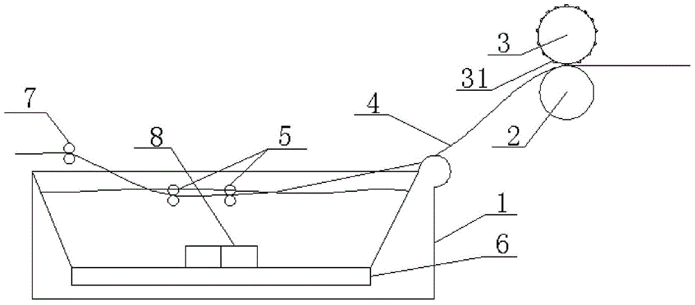
[0012] Such as figure 1 As shown, a textile printing and dyeing device of the present invention includes a printing and dyeing water tank 1, the edge of one side of the printing and dyeing water tank 1 is a smooth arc surface, and a cloth guide roller 2 is provided on the same side as the smooth arc surface edge of the printing and dyeing water tank 1, and the The surface of the cloth guide roller 2 is provided with a first electrostatic layer, the top of the cloth guide roller 2 is provided with a pressure roller 3 linked with the cloth guide roller 2, and the surface of the pressure roller 3 is provided with a protrusion 31, and the protrusion 31 has a The second ...


PUM


Abstract

The invention discloses a textile printing and dyeing device.The textile printing and dyeing device comprises a printing and dyeing water tank, the edge of one side of the printing and dyeing water tank is a smooth arc surface, a cloth guide roller is arranged on the same side of the edge of the smooth arc surface of the printing and dyeing water tank, the surface of the cloth guide roller is provided with a first electrostatic layer, a compression roller which is in linkage with the cloth guide roller is arranged on the cloth guide roller, the surface of the compression roller is provided with protrusions, and each protrusion is provided with a second electrostatic layer with the polarity opposite to that of the first electrostatic layer; at least one set of printing and dyeing compression rollers are symmetrically arranged in the printing and dyeing water tank in an up-and-down mode, a gap between every two corresponding printing and dyeing compression rollers is equal to the thickness of a fabric which is not subjected to printing and dyeing, and extrusion rollers higher than the horizontal plane of dye are arranged at the water outlet end of the fabric located in the printing and dyeing water tank.According to the textile printing and dyeing device, static electricity of the fabric and a fluff layer attached to the surface of the fabric can be eliminated before printing and dyeing are conducted, redundant dye in the printing and dyeing water tank can be discharged, the situation that due to the fact that the dye is brought out when the fabric is taken out of the dye tank, the environment is polluted is avoided, and the printing and dyeing quality can be improved.

Description

technical field [0001] The invention relates to a textile printing and dyeing device. Background technique [0002] At present, there are two main methods of printing and dyeing, one is traditional paint printing and dyeing, and the other is reactive printing and dyeing as opposed to paint printing and dyeing. Regardless of whether it is paint printing or reactive printing, the sundries on the surface of the fabric must be removed before printing and dyeing. Printing and dyeing of high-quality fabrics has very strict environmental requirements. There will be some fluff attached to the surface of the fabric, which is easy to be electrostatically adsorbed. Dye crosses the line, resulting in uneven printing and dyeing. Contents of the invention [0003] The technical problem to be solved by the present invention is to overcome the defects of the prior art and provide a textile printing and dyeing device. [0004] In order to solve the problems of the technologies described ...

Claims


Application Information

Patent Timeline
Patent Type & Authority Applications(China)
IPC IPC(8): D06B3/18D06B23/02D06B23/20D06B23/22
Inventor 顾晓丹
Owner CHANGSHU SHUNWANG NETWORK TECH SERVICE CO LTD
Learn More