
Lifting device and inverted installing method for reducing absorption tower

An absorption tower and inversion technology, which is applied in the field of inversion of variable diameter absorption towers, can solve the problems of variable diameter absorption towers such as complicated procedures, slow progress, and difficult control of installation quality

Active Publication Date: 2016-07-20
HUNAN THERMAL POWER CONSTR CO LTD OF CHINA ENERGY ENG GRP
View PDF4 Cites 17 Cited by
  • Summary
  • Abstract
  • Description
  • Claims
  • Application Information

AI Technical Summary

Problems solved by technology

The installation methods of the absorption tower include: frontal installation method and inverted installation method. The frontal installation method is assembled with one or two truck cranes, and the installation starts from the first layer and goes up layer by layer; Assemble downwards layer by layer. Both the front-mounting method and the traditional flip-chip method have the disadvantages of slow progress, large investment of manpower, and difficulty in controlling the installation accuracy and welding quality. The installation process of the variable-diameter absorption tower is more complicated and Installation quality is more difficult to control

Method used


Image

  • Lifting device and inverted installing method for reducing absorption tower
  • Lifting device and inverted installing method for reducing absorption tower
  • Lifting device and inverted installing method for reducing absorption tower

Examples


Embodiment Construction

[0092] Attached below Figure 1 to Figure 10 Embodiments of the present invention are described in detail.

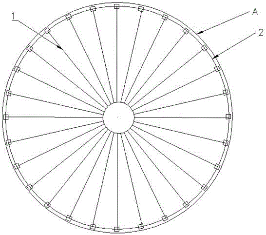
[0093] As shown in the figure, the lifting device includes a hydraulic lifting circular frame 1, an expansion ring 2 attached to the inner wall of the cylinder, and a door-shaped steel clip 3 for fixing the expansion ring. The door-shaped steel clip 3 is buckled on the expansion ring 2 and connected with The inner wall of the cylinder is welded and fixed, and the hydraulic lifting circular frame 1 includes hydraulic lifting frames 11 uniformly distributed on the inner side of the cylinder A along the circumference, a central steel pipe 12 arranged in the center of the cylinder A, and successively connected to the circumferential direction of each hydraulic lifting frame 11. Channel steel 13 and the radial channel steel 14 that is used to connect central steel pipe 12 and hydraulic lifting frame 11, hydraulic lifting frame 11 and central steel pipe 12 are all welded and ...


PUM

PropertyMeasurementUnit
Heightaaaaaaaaaa
Lengthaaaaaaaaaa
Heightaaaaaaaaaa

Abstract

The invention discloses a lifting device used for lifting a large cylinder during inverted installing of an absorption tower. The lifting device comprises a hydraulic lifting round frame, an expansion ring attached to the inner wall of the cylinder, and door-shaped steel clamps used for fixing the expansion ring. The door-shaped steel clamps are buckled on the expansion ring and welded and fixed to the inner wall of the cylinder. The hydraulic lifting round frame comprises hydraulic lifting frames evenly arranged on the inner side of the cylinder along the circumference, a center steel pipe arranged in the center position of the cylinder, circumferential box iron sequentially connected with the hydraulic lifting frames, and radial box iron used for connecting the center steel pipe with the hydraulic lifting frames. The hydraulic lifting frames and the center steel pipe are all welded and fixed to a bottom plate. Each hydraulic lifting frame comprises a support, an oil cylinder arranged over the support, a lifting rod, an upper clamping head arranged over the oil cylinder and used for driving the lifting rod to move upwards, a lower clamping head arranged between the support and the oil cylinder and used for limiting downward sliding of the lifting rod, and a sliding pull block capable of sliding along the support. According to an inverted installing method for the reducing absorption tower, the installing procedures of the absorption tower are simplified, and the installing quality of the absorption tower is improved.

Description

technical field [0001] The invention relates to a lifting device used for the installation of a desulfurization absorption tower. The invention also relates to an upside-down method of the variable-diameter absorption tower. Background technique [0002] In recent years, large-scale supercritical units and above have gradually become the main units of thermal power plants. According to the relevant regulations of the country on energy conservation, emission reduction and environmental protection: the design, construction and operation of boiler flue gas desulfurization systems in thermal power plants must be carried out at the same time run. [0003] Limestone-gypsum wet desulfurization process is generally used for boiler flue gas desulfurization, and the flue gas desulfurization absorption tower is one of the important equipment for this process. Due to the characteristics of large volume, wide inner diameter and heavy weight, the absorption tower needs to be combined an...

Claims


Application Information

Patent Timeline
IPC IPC(8): B66F7/08B66F7/28B01D53/18
CPCB01D53/18B01D2257/30B01D2258/0283B66F7/08B66F7/28
Inventor 陈步书谭杰
Owner HUNAN THERMAL POWER CONSTR CO LTD OF CHINA ENERGY ENG GRP
Learn More