Eureka AIR delivers breakthrough ideas for toughest innovation challenges, trusted by R&D personnel around the world.

Control device, equipment and method for controlling electrohydrodynamics printing resolution

A control device and dynamics technology, applied in the direction of improvement of process efficiency, additive manufacturing, energy efficiency, etc., can solve the printing limitation of high resolution, the resolution is difficult to be further improved, and the electrohydrodynamic printing technology is difficult to meet High-resolution micro-nano device printing requirements and other issues, to achieve the effect of improving resolution

Active Publication Date: 2016-07-20
JIAXING UNIV
View PDF8 Cites 24 Cited by
  • Summary
  • Abstract
  • Description
  • Claims
  • Application Information

AI Technical Summary

Problems solved by technology

[0004] To sum up, the existing electrohydrodynamic printing method is limited to high-resolution printing, and its resolution is difficult to be further improved. Device Printing Requirements
[0005] The Chinese invention patent with the application number CN201510966964.6 and the publication date of March 2, 2016 discloses a 3D metal printing system based on magnetic field regulation. By adjusting the deflection magnetic field strength of the printing positioning device in real time, the trajectory of the charged metal droplet can be changed. , to achieve accurate accumulation on the platform of the model placement device, this method does not involve controlling the resolution of electrohydrodynamic printing

Method used


Image

  • Control device, equipment and method for controlling electrohydrodynamics printing resolution
  • Control device, equipment and method for controlling electrohydrodynamics printing resolution
  • Control device, equipment and method for controlling electrohydrodynamics printing resolution

Examples


Embodiment Construction

[0025] Embodiments of the present invention will be further described below in conjunction with accompanying drawings:

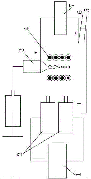
[0026] The present invention provides: a control device for controlling the resolution of electrohydrodynamic printing, which includes a magnetic field generating device 4 for generating centripetal Lorentz force, and a magnetic field generating device 4 connected with the magnetic field generating device 4 for adjusting the centripetal Lorentz force A controller 1 of the magnitude of the force, the controller 1 is connected with two visual detection devices 2, and the visual detection device 2, the controller 1 and the magnetic field generator 4 form a closed-loop control loop.

[0027] The magnetic field generating device 4 is composed of at least one annular electromagnetic induction coil wound on the annular iron core, a plurality of annular iron cores are stacked, and each annular iron core is wound with an annular electromagnetic induction coil respecti...


PUM


Abstract

The invention provides a control device, equipment and method for controlling the electrohydrodynamics printing resolution. The control device for controlling the electrohydrodynamics printing resolution comprises a magnetic field generation device used for generating centripetal Lorentz force and a controller connected with the magnetic field generation device. The controller is connected with two vision detection devices. A closed-loop control circuit is formed by the vision detection devices, the controller and the magnetic field generation device. An annular magnetic field is generated through an annular electromagnetic induction coil in a jetted liquid drop flying area, the movement of electrified liquid drops in the annular magnetic field is subjected to the effect of the centripetal Lorentz force, control parameters of the control device are adjusted in real time according to detection results of the vision detection devices so that the centripetal Lorentz force can be changed, the movement of the electrified liquid drops is effectively restrained, diffusion of the liquid drops to the periphery is restrained, the flying angle of the liquid drops is reduced, and therefore the electrohydrodynamics printing resolution is increased.

Description

technical field [0001] The invention relates to the technical field of electrohydrodynamic printing, in particular to a control device for controlling the resolution of electrohydrodynamic printing, printing equipment and a control method. Background technique [0002] Inkjet printing technology has received extensive attention in micro-nano processing technology, such as flexible electronic circuits, wearable electronic devices, solar cells, biological functional devices, microfluidic chips, etc. The traditional inkjet printing method usually adopts the thermal bubble type and the piezoelectric type driving method. They all adopt the push driving principle. The line width of inkjet printing is generally 20-50um. As the size of the nozzle decreases, it takes More pressure, and solution viscosity makes nozzles more likely to clog. For thermal bubble inkjet printing, heating is required, but high temperature will affect the performance of the ink; for piezoelectric inkjet pri...

Claims


Application Information

Patent Timeline
IPC IPC(8): B22F3/105B33Y30/00B33Y40/00
CPCB33Y30/00B33Y40/00B22F10/00B22F10/18B22F10/22B22F10/85B22F12/90Y02P10/25
Inventor 张礼兵左春柽黄风立吴婷鹿业波
Owner JIAXING UNIV
Why Eureka
Eureka Blog
Learn More