
A method and device for detecting distance using distance sensor

A technology of distance sensor and distance detection, which is applied in the direction of measuring devices, using re-radiation, instruments, etc., and can solve the problem of inaccurate distance measurement

Active Publication Date: 2018-01-16
SHANGHAI KOHLER ELECTRONICS TECH
View PDF5 Cites 0 Cited by
  • Summary
  • Abstract
  • Description
  • Claims
  • Application Information

AI Technical Summary

Problems solved by technology

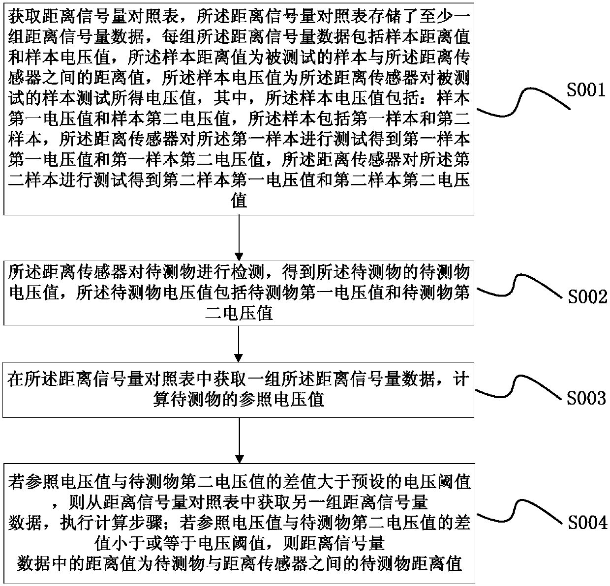
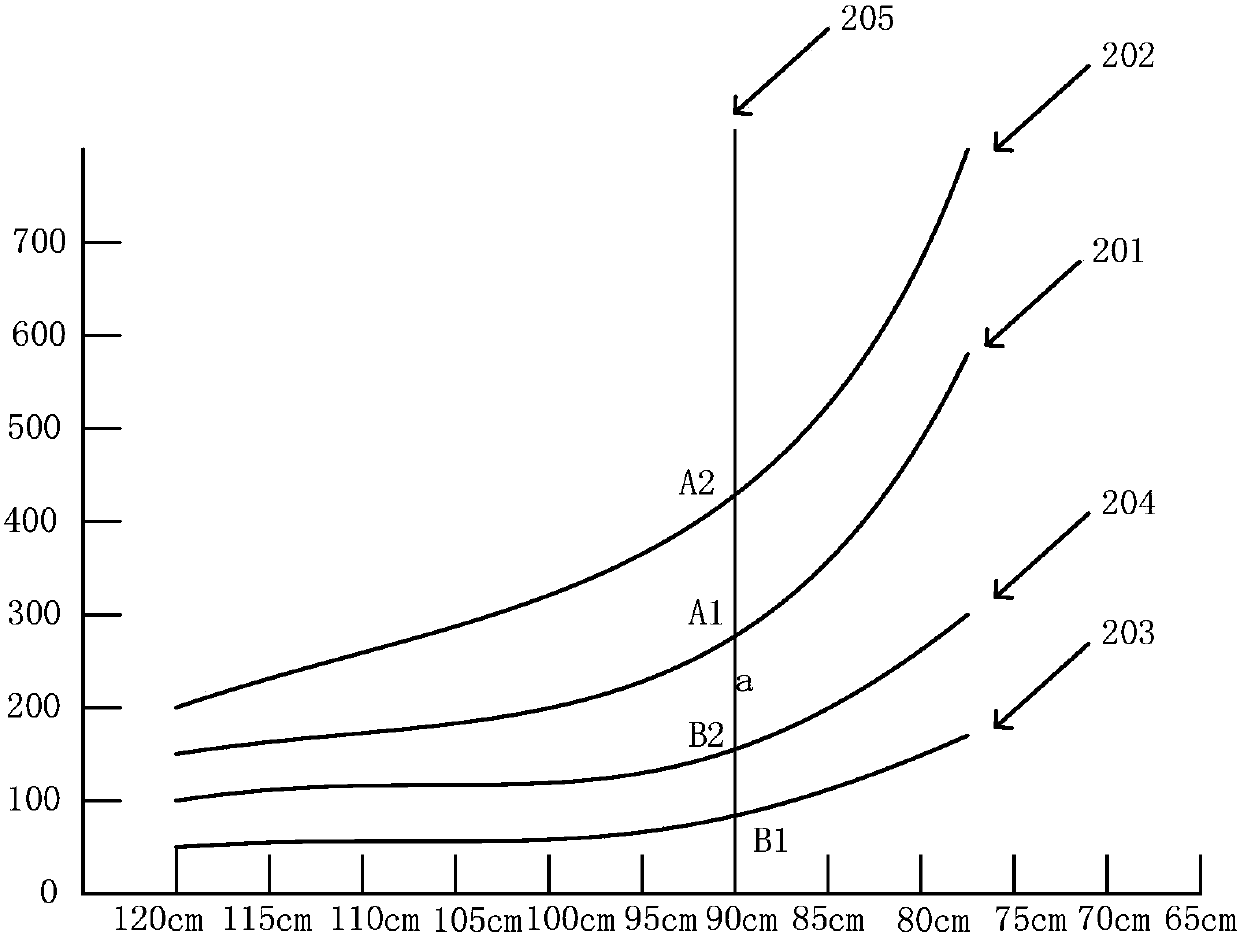
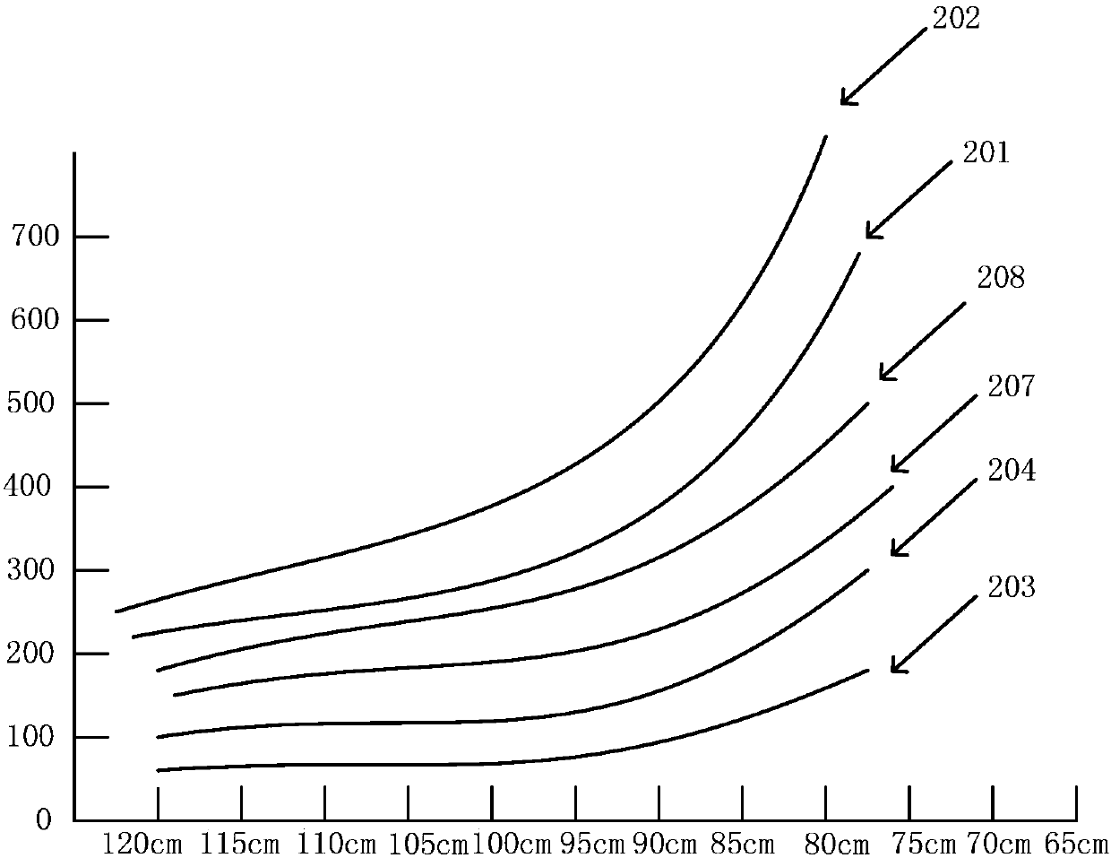
[0004] Based on the above problems, the present invention proposes a method for detecting distance using a distance sensor. By obtaining the distance semaphore comparison table, the distance semaphore comparison table stores at least one set of distance semaphore data, and each group of distance semaphore data includes sample distance values. and the sample voltage value; the distance sensor detects the object to be measured to obtain the voltage value of the object to be measured, and the voltage value of the object to be measured includes the first voltage value of the object to be measured and the second voltage value of the object to be measured; Obtain a set of distance semaphore data from the comparison table, and calculate the reference voltage value of the object under test according to the formula; Obtain another set of distance semaphore data from the table, and perform calculation steps; if the difference between the reference voltage value and the second voltage value of the object under test is less than or equal to the voltage threshold, the distance value in the distance semaphore data is between the object under test and The distance value of the object to be measured between the distance sensors solves the problem of inaccurate distance measurement by the PSD infrared sensing module in the prior art

Method used


Image

  • A method and device for detecting distance using distance sensor
  • A method and device for detecting distance using distance sensor
  • A method and device for detecting distance using distance sensor

Examples


Embodiment Construction

[0068] The present invention will be further described in detail below in conjunction with specific embodiments and accompanying drawings. It is only intended to describe the specific implementation of the present invention in detail, and does not impose any limitation on the present invention, and the scope of protection of the present invention shall be determined by the claims.

[0069] refer to figure 1 , the present invention proposes a method for utilizing a distance sensor to detect a distance, comprising:

[0070] The step of obtaining the comparison table includes: obtaining the distance semaphore comparison table, the distance semaphore comparison table stores at least one set of distance semaphore data, each set of distance semaphore data includes sample distance values ​​and sample voltage values, and the sample distance values ​​are tested The distance value between the sample and the distance sensor, the sample voltage value is the voltage value obtained by the ...


PUM


Abstract

The invention puts forward a method and a device for detecting distance through use of a distance sensor. The method comprises a comparison table acquiring step, a detection step, a calculation step, and a distance determining step. In the comparison table acquiring step, a distance semaphore comparison table is acquired, wherein the distance semaphore comparison table stores at least one group of distance semaphore data. In the detection step, a distance sensor detects a to-be-detected object to get the to-be-detected object voltage values of the to-be-detected object, wherein the to-be-detected object voltage values include a first to-be-detected object voltage value and a second to-be-detected object voltage value. In the calculation step, one group of distance semaphore data is acquired from the distance semaphore comparison table, and the reference voltage value of the to-be-detected object is calculated according to a formula. In the distance determining step, the distance between the to-be-detected object and the distance sensor is determined according to the difference between the reference voltage value and the second to-be-detected object voltage value. The problem of inaccurate distance measurement due to calculation error caused by PSD infrared sensing module processing and installing difference in the prior art is solved.

Description

technical field [0001] The invention relates to the field of sensor ranging, in particular to a method and device for detecting distance by using a distance sensor. Background technique [0002] The distance measurement principle of the traditional PSD (position sensitive detector) infrared sensor module is mainly: relying on the optical principle and trigonometric function relationship to calculate the distance value of the measured object, so when using this method for distance measurement, the installation position of the PSD infrared sensor module is required It is very strict, and the requirements for the optical lens processing process of the PSD infrared sensor module are also very strict. In the process of actual mass production of PSD infrared sensing modules, it is difficult to guarantee the consistency of the installation position of the PSD infrared sensing module and the processing of the optical lens, which eventually leads to the difference between the distanc...

Claims


Application Information

Patent Timeline
Patent Type & Authority Patents(China)
IPC IPC(8): G01S11/12
CPCG01S11/12
Inventor 彭灿辉
Owner SHANGHAI KOHLER ELECTRONICS TECH
Learn More