
Lane Change Control Device And Control Method

一种车道变换、控制装置的技术,应用在控制装置、车辆配件、车辆部件等方向,能够解决事故、碰撞等问题

Active Publication Date: 2016-07-13
HL KLEMOVE CORP
View PDF5 Cites 60 Cited by
  • Summary
  • Abstract
  • Description
  • Claims
  • Application Information

AI Technical Summary

Problems solved by technology

[0006] Although the camera sensor has the advantage of a wide field of view, the camera sensor connected to the lane change device is only used as a sensor to sense objects in the blind spot and warn the driver
[0007] However, here's the problem: Drivers who are physically disabled or fail to recognize the warning due to surrounding conditions can cause accidents when trying to change lanes
[0010] However, there is a problem that, unlike the lane keeping assist system that recognizes the lane and controls the vehicle so as not to deviate from the lane through steering control, the operation of the lane change control system needs to monitor the condition of the adjacent lane to which the current lane is to be changed, set the The path of lane changes and the complex process of implementing vehicle speed or steering angle control
[0011] Furthermore, during the course of the lane change control there is the risk of a collision with another vehicle driving in the adjacent lane, for example

Method used


Image

  • Lane Change Control Device And Control Method
  • Lane Change Control Device And Control Method
  • Lane Change Control Device And Control Method

Examples


Embodiment Construction

[0030] Some embodiments of the present invention will be described in detail below with reference to exemplary drawings. In describing elements of the present invention, the terms "first", "second", "A", "B", "(a)", "(b)", etc. may be used. These terms are only used to distinguish one structural element from other structural elements, and the properties, order, sequence, etc. of the corresponding structural elements are not limited by the terms. It should be noted that when it is described in the specification that one component is "connected", "coupled" or "engaged" to another component, although the first component may be directly connected, coupled or coupled to the second component, the A third component may be "connected", "coupled" or "engaged" between the first component and the second component. It will be noted that, regarding the nomenclature of elements, "own vehicle" and "vehicle" refer to the same element.

[0031] figure 1 is a diagram illustrating the configu...


PUM


Abstract

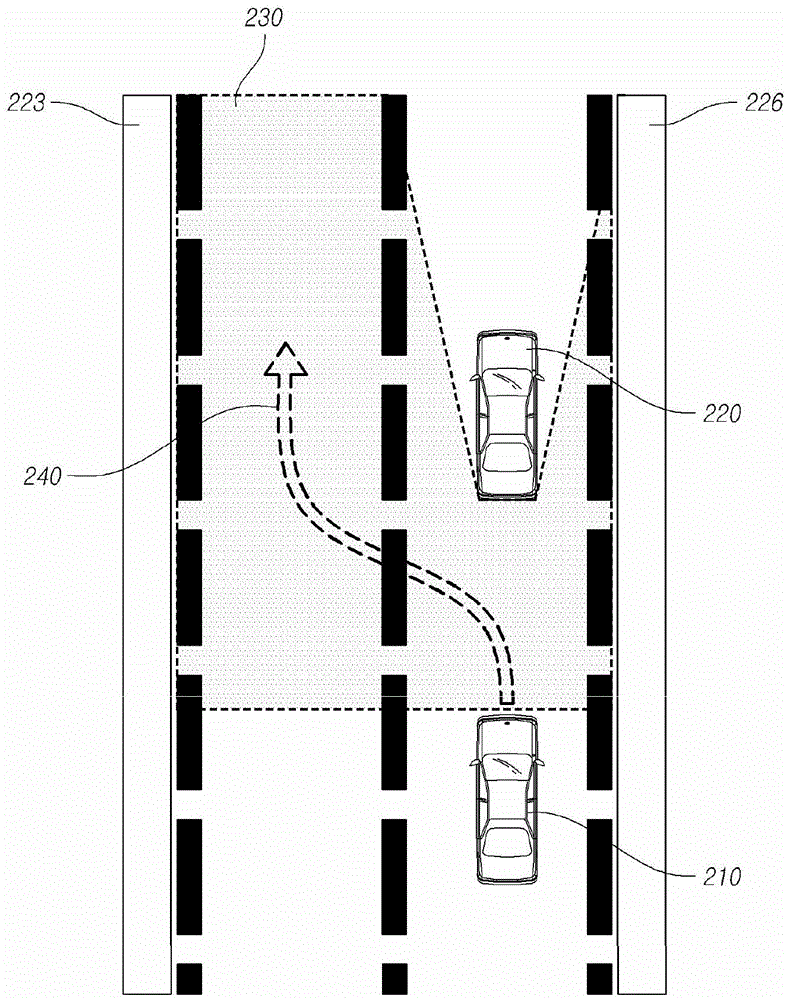
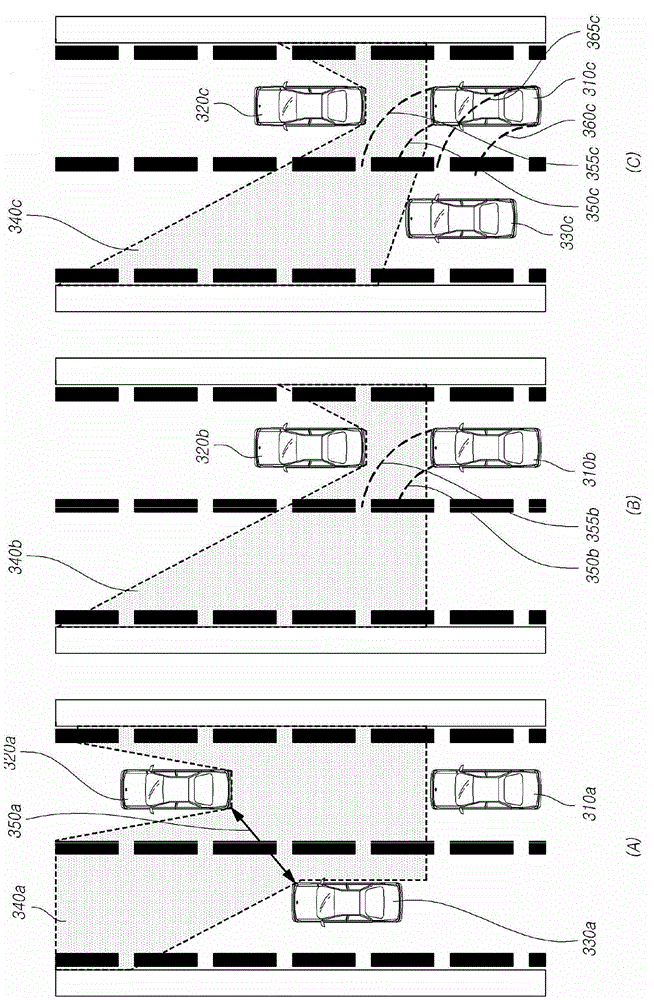
The present disclosure relates to a technology for changing lane in which a vehicle is driving, in particular to a lane change control device. The lane change control device comprises a space recognition unit that detects a front object by using a camera sensor of the vehicle, recognizes an empty space in which the front object does not exists, and determines a target position, within the empty space on the basis of a lane modeling equation determined from a lateral offset, the vehicle's traveling velocity (V), and a lane change request time (t), wherein the lateral offset is the distance between the center of the camera sensor and the center of the adjacent lane; a path generation unit that generates a path for moving from a current vehicle position to the target position; and a control unit that performs a lane change control that controls at least one of the vehicle's steering angle and a vehicle velocity such that the vehicle moves to the target position along the path. By the lane change control device, the automatic lane change control of the vehicle can be realized possibly.

Description

[0001] Cross References to Related Applications [0002] This application claims priority from Korean Patent Application No. 10-2014-0193119 filed on December 30, 2014, which is incorporated herein by reference in its entirety. technical field [0003] The present invention relates to techniques for changing the lane in which a vehicle is currently traveling. More specifically, the present invention relates to a technique for changing lanes based on the condition of an object in front of the vehicle. Background technique [0004] Generally, vehicles have camera sensors installed to recognize external objects. [0005] This camera sensor can sense a wide field of view and it is used as a sensor of another device. [0006] Although the camera sensor has the advantage of a wide field of view, the camera sensor connected to the lane change device is only used as a sensor to sense objects in the blind spot and warn the driver. [0007] Here's the problem, however: Drivers who ...

Claims


Application Information

Patent Timeline
Patent Type & Authority Applications(China)
IPC IPC(8): B60W30/18B60W40/02B60W10/06B60W10/20B60W10/18
CPCB60W10/06B60W10/18B60W10/20B60W30/18B60W40/02B60W40/072B60W2520/10B60W2520/105B60W2540/18B60W2554/801B60R2300/804B60R2300/8086B62D15/0255B60W30/18163B60W10/04B60W2710/207B60W2720/10B60W2540/20G06V20/588G06V20/58B60W2420/403B60R21/0134B60W30/095Y02T10/84B60K31/0008B60R11/04
Inventor 沈相均
Owner HL KLEMOVE CORP
Learn More