
Main transformer chamber ventilation device capable of noise reduction

A technology for a ventilation device and a main transformer room is applied in the field of noise reduction in substations, which can solve the problems affecting the noise control of the main transformer room, poor heat dissipation of the main transformer, unreasonable arrangement of shutters and ventilation fans, etc., achieving great practical value and improving ventilation. The effect of heat dissipation

Inactive Publication Date: 2016-07-06
STATE GRID TIANJIN ELECTRIC POWER +2
View PDF6 Cites 1 Cited by
  • Summary
  • Abstract
  • Description
  • Claims
  • Application Information

AI Technical Summary

Problems solved by technology

[0002] Ventilation, heat dissipation and noise in the main transformer room of the substation have always been difficult problems to solve. During the operation of the transformer, a large amount of heat will be generated and air exchange is required to take the heat out of the room. This requires the installation of more ventilation louvers in the main transformer room. , so that the air enters the main transformer room, and then the hot air is drawn out of the main transformer room through the ventilation fan and discharged to the outside. At the same time, the transformer and fan will also emit a lot of noise during operation.
There are two problems in this process: 1. The louvers of the main transformer room will affect the noise control of the main transformer room, causing noise nuisance; If it is in full contact with the heat sink of the transformer for convective heat transfer, it will be drawn out of the room, making the heat dissipation of the main transformer poor and causing the main transformer room to overheat

Method used


Image

  • Main transformer chamber ventilation device capable of noise reduction

Examples


Embodiment Construction

[0010] The embodiments of the present invention are described in further detail below in conjunction with the accompanying drawings: It should be emphasized that the embodiments of the present invention are illustrative rather than restrictive, so the present invention is not limited to the implementation described in the specific embodiments. For example, all other implementations obtained by those skilled in the art according to the technical solution of the present invention also belong to the protection scope of the present invention.

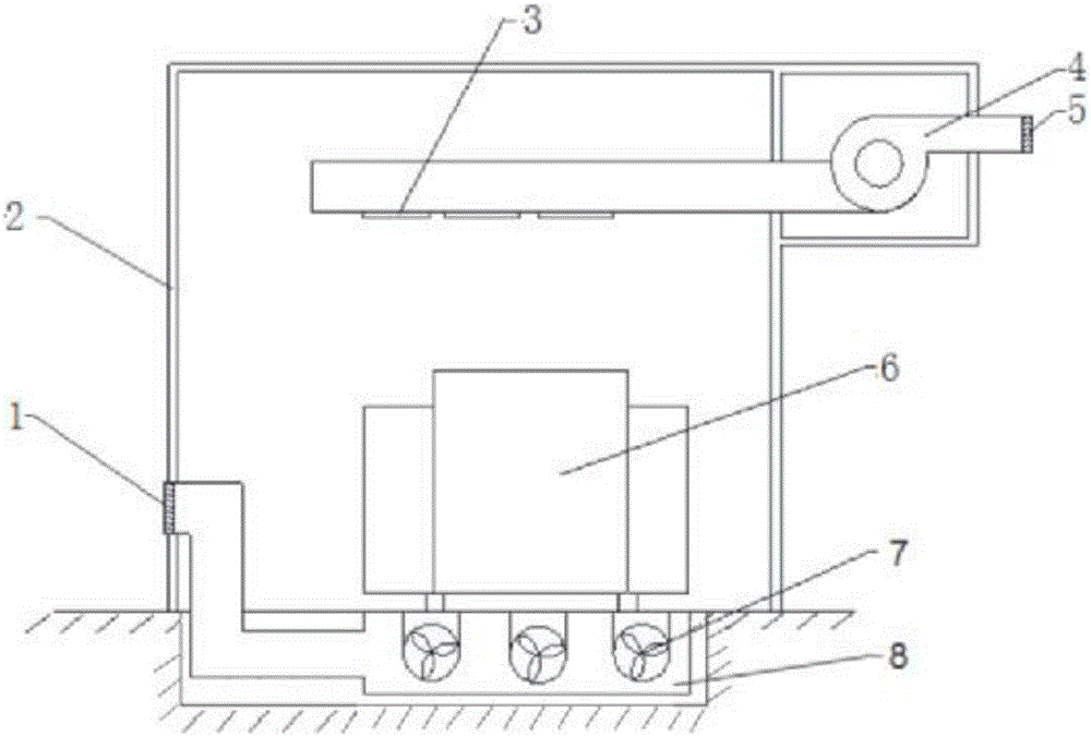
[0011] A main transformer room ventilation device for reducing noise, such as figure 1 As shown, the main transformer room 2 is included, and the transformer 6 is installed on the floor of the main transformer room. The floor is connected, and the other end is connected to the exhaust duct 8 of the side wall of the main transformer room. An exhaust fan 7 is installed on the side below the floor of the exhaust duct, and an exhaust muffler lo...


PUM


Abstract

The invention relates to a main transformer chamber ventilation device capable of noise reduction. The main transformer chamber ventilation device comprises a main transformer chamber and a transformer, wherein a pore passage is formed under the main transformer chamber, an exhaust duct is arranged in the pore passage, an exhaust fan is arranged on one side below an exhaust duct floor, a ventilation sound attenuation shutter is arranged at an outlet on the other side, an isolation interval of a centrifugal fan is arranged outside the top of a side wall of the main transformer chamber, an air inlet pipeline of the centrifugal penetrates out of the isolation interval to be communicated with atmosphere, an air inlet sound attenuation shutter is arranged at an air inlet pipeline port, an air supply pipeline of the centrifugal passes through the side wall of the main transformer chamber and extends to a part above the transformer, a plurality of air supply holes are uniformly formed in the air supply pipeline above the transformer at equal intervals and are provided with downward openings. By the main transformer chamber ventilation device, the ventilation and cooling capability of the main transformer chamber can be greatly improved, meanwhile, the noise of the main transformer chamber is effectively controlled to be transferred to the outside, and the main transformer chamber ventilation device has relatively high practical value.

Description

technical field [0001] The invention belongs to the technical field of substation noise reduction, in particular to a main transformer room ventilation device for reducing noise. Background technique [0002] Ventilation, heat dissipation and noise in the main transformer room of the substation have always been difficult problems to solve. During the operation of the transformer, a large amount of heat will be generated and air exchange is required to take the heat out of the room. This requires the installation of more ventilation louvers in the main transformer room. , so that the air enters the main transformer room, and then the hot air is drawn out of the main transformer room by the ventilation fan and discharged to the outside. At the same time, the transformer and the fan will also emit a lot of noise during operation. There are two problems in this process: 1. The louvers of the main transformer room will affect the noise control of the main transformer room, causin...

Claims


Application Information

Patent Timeline
IPC IPC(8): H02B1/56H02B1/26
CPCH02B1/26H02B1/56
Inventor 王桂林周连升刘新利李丛林徐元孚张宇周义刚薛泽海边疆王森
Owner STATE GRID TIANJIN ELECTRIC POWER
Learn More