
Overlaid insulating flexible busbar

A flexible busbar and insulating layer technology, applied in the direction of insulators, organic insulators, plastic/resin/wax insulators, etc., can solve the problems of cable wiring assembly confusion, insulation heat shrinkable sleeves, falling off, etc.

Inactive Publication Date: 2016-07-06
SUZHOU CURRENT POWER TECH CO LTD
View PDF7 Cites 5 Cited by
  • Summary
  • Abstract
  • Description
  • Claims
  • Application Information

AI Technical Summary

Problems solved by technology

[0003] However, due to the constant vibration during the operation of the electric vehicle, the vibration between the battery pack, the drive motor and the control unit will cause the connection part of the end to loosen, or even cause it to fall off, and due to the large current, the cable needs to be very thick , the turning and wiring assembly of cables inside the car is very confusing, and the temperature is high; there are too many types of soft connections using insulating heat shrinkable sleeves, and it is easy to use them wrong; for wind power generation and solar power generation industries that use IGBTs, bare copper bars are used. Or add epoxy resin boards between the copper bars and use laminated busbars for insulation and power distribution. The assembly size requirements between the rows are high, and on-site assembly and adjustment are difficult. The ambient temperature changes with the four seasons will also cause laminated busbars. Thermal expansion and contraction of the row, resulting in changes in installation dimensions and affecting use

Method used


Image

  • Overlaid insulating flexible busbar
  • Overlaid insulating flexible busbar

Examples


Embodiment

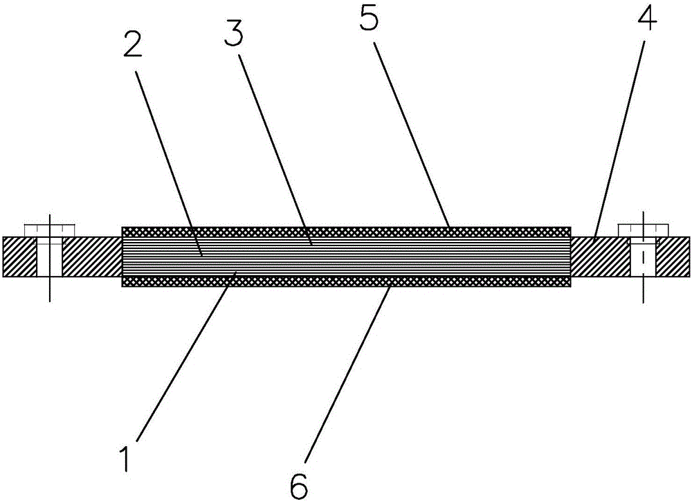
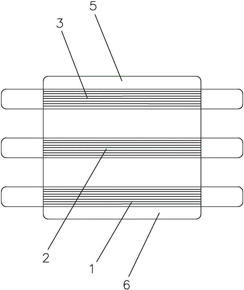
[0025] like figure 1 and figure 2 As shown, a laminated insulated flexible bus bar includes a soft connection copper bar 1, a soft connection copper bar 2 and a soft connection copper bar 3, and the soft connection copper bar 1, the soft connection copper bar 2 and the soft connection copper bar 3 There are fixed connection parts 4 at both ends, and the soft connection copper bar 1, the soft connection copper bar 2, the soft connection copper bar 3 and the fixed connection part 4 are all made of semi-hard T2 pure copper, and the fixed connection part 4 is set At both ends of the laminated insulated flexible busbar, the soft connection copper bar 1, soft connection copper bar 2 and soft connection copper bar 3 are arranged in the middle of the laminated insulated flexible busbar, and the soft connection copper bar 1, soft connection copper bar 2 and the two ends of the flexible connection copper bar 3 are respectively connected to the inner side of the fixed connection part 4...


PUM

PropertyMeasurementUnit
Thicknessaaaaaaaaaa

Abstract

The laminated insulated flexible bus bar includes at least three layers of flexible connection copper bars, and fixed connection parts are provided at both ends of the flexible connection copper bars, and the soft connection copper bars and fixed connection parts are made of T2 pure copper, and the fixed connection parts are located on At both ends of the laminated insulated flexible bus bar, the soft connection copper bar is arranged in the middle of the laminated insulated flexible bus bar, and the two ends of the soft connection copper bar are respectively connected to the inner side of the fixed connection part; the soft connection copper bar includes multi-layer laminated together Copper foil layer, the top and bottom surfaces of the laminated multilayer copper foil layer are respectively fixed with an upper insulating layer and a lower insulating layer, and the two ends of the multilayer copper foil layer are welded to each other by polymer diffusion welding or ultrasonic welding. The inner ends of the two fixed connection parts. This bus bar can be connected in different orientations, different heights, different planes and multiple orientations, and has good vibration resistance and firm connection, such as being used for the non-stop vibration during the operation of the electric vehicle, between the battery pack, the drive motor and the control It will not cause the connection part of the end to loosen or fall off between the units.

Description

technical field [0001] The invention relates to the field of power supply and distribution equipment, in particular to a laminated insulating flexible bus bar. Background technique [0002] At present, in the new energy vehicle industry, electric vehicles and plug-in range-extended vehicles are connected to the battery pack with cables or flexible connections of insulated heat-shrinkable sleeves; in the charging unit, cables or copper bars are used to connect The AC power is connected to high-power components such as the inverter unit and IGBT, and the connection between the control unit and the drive motor is powered by cables. For industries such as uninterruptible power supplies, bare copper bars are used for power distribution. In the DC-to-AC or AC-to-DC inverter units of wind power generation, solar power generation and other industries, bare copper bars are used or epoxy resin boards are added between copper bars for insulation or laminated bus bars are used for dist...

Claims


Application Information

Patent Timeline
IPC IPC(8): H01B3/42H01B9/00B32B15/09B32B15/20
CPCH01B9/006B32B15/09B32B15/20H01B3/421
Inventor 朱国清杨建锋夏景须
Owner SUZHOU CURRENT POWER TECH CO LTD
Learn More