A Dynamic Loading and Unloading Rod Structure for Raise Drilling Rig

A kind of raise drilling rig, dynamic technology, applied in the direction of drill pipe, drill pipe, drilling equipment, etc., can solve the problems of slow unloading, inconvenient operation, etc., to achieve the effect of convenient operation and fast clamping

Active Publication Date: 2018-04-13
HUNAN CHUANGYUAN HIGH TECH MACHINERY CO LTD
View PDF6 Cites 0 Cited by
  • Summary
  • Abstract
  • Description
  • Claims
  • Application Information

AI Technical Summary

Problems solved by technology

It uses the swing of the rod unloading wrench of the hydraulic unloading device to loosen the connecting thread between the drill pipe and the drill pipe, but the unloading of the rod is slow and the operation is inconvenient

Method used


Image

  • A Dynamic Loading and Unloading Rod Structure for Raise Drilling Rig
  • A Dynamic Loading and Unloading Rod Structure for Raise Drilling Rig
  • A Dynamic Loading and Unloading Rod Structure for Raise Drilling Rig

Examples


Embodiment

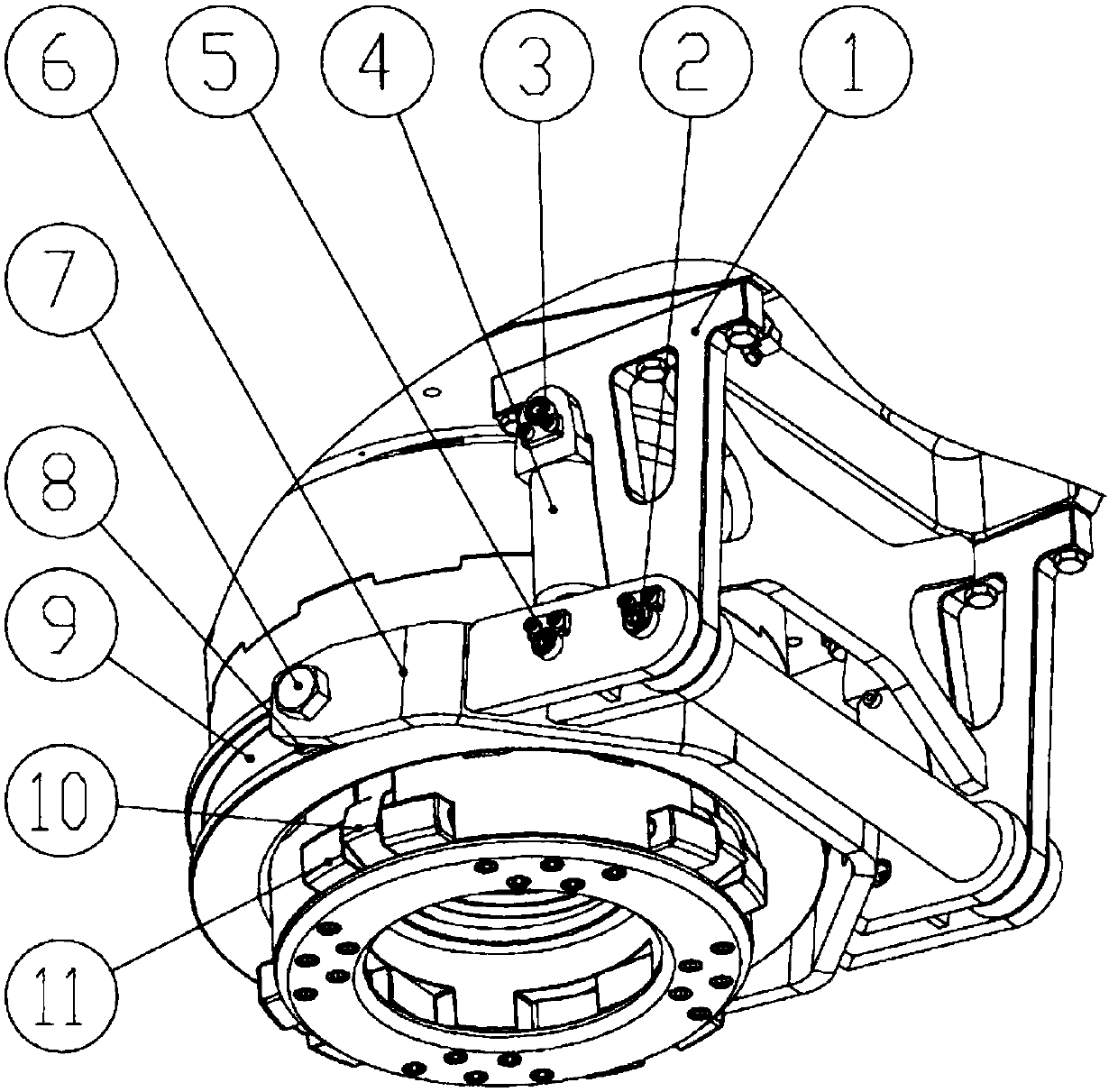
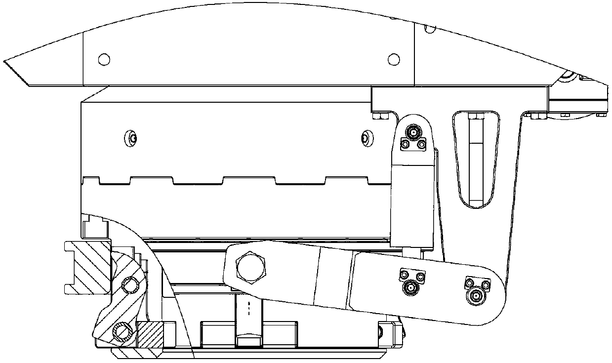
[0025] Such as figure 1 , 2 As shown, a dynamic loading and unloading rod structure for a raise drilling rig provided by the present invention includes a mounting seat 1, a lifting arm 6, an oil cylinder 4, a driving sleeve 9, a slider 8, a shifting block 10 and a clamping block 11. The mounting base 1 is connected with the slewing head box, the cylinder barrel of the oil cylinder 4 is connected with the mounting base 1 through the cylinder pin 3, and the mounting base 1 is connected with the lifting arm pin 2 6, the piston rod of the oil cylinder 4 is connected with the lifting arm 6 through the piston rod pin 5, the slider 8 is connected with the lifting arm 6 through the slider pin 7, and the slider 8 Snap into the chute of the driving sleeve 9, the shifting block 10 is connected with the head body of the rotary power head through the upper pin shaft, and the shifting block 10 is connected with the clamping block 11 through the lower pin shaft.

[0026] The oil cylinder 4...


PUM


Abstract

The invention discloses a dynamic upper rod disassembling structure for a raise boring machine. The dynamic upper rod disassembling structure comprises a mounting base, a lifting arm, a cylinder, a driving sleeve, a sliding block, a shifting block and a clamping block, wherein the mounting base is connected with a rotary box body; the cylinder drum of the cylinder is connected with the mounting base through a cylinder drum hinge pin; the mounting base is connected with the lifting arm through the lifting arm hinge pin; the piston rod of the cylinder is connected with the lifting arm through the piston rod hinge pin; the sliding block is connected with the lifting arm through a sliding block pin; the sliding block is clamped into a sliding groove of the driving shaft; the shifting block is connected with a rotary power head machine head body through an upper hinge pin; the shifting block is connected with the clamping block through a lower pin shaft. By adopting the dynamic upper rod disassembling structure, a drilling rod of the raise boring machine can be rapidly clamped, so that a drilling rod can be rapidly disassembled, and the operation can be convenient.

Description

technical field [0001] The invention belongs to the technical field of mining machinery, in particular to a dynamic loading and unloading rod structure for a raise drilling machine. Background technique [0002] Raise drilling rig is an important construction equipment in mine raise construction. During the construction process, the auxiliary operation time often becomes an important factor affecting the construction efficiency of raise drilling rig. How to quickly clamp the drill pipe to realize the quick disassembly of the drill pipe thread to reduce the auxiliary operation time is an important aspect that needs to be studied, and it is also an urgent problem to be solved to improve the operating efficiency of the raise drilling rig. As disclosed in Patent No. 201220347247.7, a down-the-hole drilling machine with a hydraulic rod unloading device includes a carriage, and a positioner seat plate installed on the carriage, and a through hole for receiving a drill rod is provi...

Claims


Application Information

Patent Timeline
Patent Type & Authority Patents(China)
IPC IPC(8): E21B19/18
CPCE21B19/18
Inventor 王毅唐安平代建龙梁宁宁
Owner HUNAN CHUANGYUAN HIGH TECH MACHINERY CO LTD
Why Eureka
Try Eureka