
Movable wall lifting mechanism

A technology for connecting shafts and fixing devices, applied in the field of movable wall lifting mechanisms, can solve the problems of affecting construction progress, low work efficiency, and increasing construction costs.

Inactive Publication Date: 2016-07-06
WENDENG LANDAO ARCHITECTURAL ENG CO LTD
View PDF0 Cites 1 Cited by
  • Summary
  • Abstract
  • Description
  • Claims
  • Application Information

AI Technical Summary

Problems solved by technology

However, the above-mentioned installation method requires the cooperation of multiple operators to complete the installation of the wall. During the installation process, the labor intensity is relatively high, and the work efficiency is low, which affects the construction progress and increases the construction cost. Very prone to safety hazards

Method used


Image

  • Movable wall lifting mechanism

Examples


Embodiment Construction

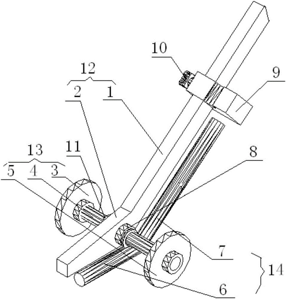
[0019] The core of the present invention is to provide a movable wall lifting mechanism, in order to realize wall lifting and adjust the wall installation position during the wall installation process, reduce labor, improve work efficiency, save construction cost, and avoid safety hazards at the same time.

[0020] In order to enable those skilled in the art to better understand the technical solutions of the present invention, the present invention will be further described in detail below in conjunction with the accompanying drawings.

[0021] Please refer to figure 1 , figure 1 It is a structural representation of a specific embodiment of the wall raising mechanism provided by the present invention.

[0022] In a specific embodiment, the wall lifting mechanism provided by the present invention includes a lifting device 12, a supporting device 14, a fixing device 9 and a walking device 13; the lifting device 12 includes a wall lifting part 2 and a handle part 1, A right an...


PUM


Abstract

The invention discloses a movable wall lifting mechanism. The movable wall lifting mechanism comprises a warping device, a supporting device, a fixing device and a walking device, wherein the warping device comprises a wall lifting part and a handheld part; a right angle or an obtuse angle is formed between the wall lifting part and the handheld part; the fixing device is glidingly arranged on the handheld part along a connection shaft; a locking device is arranged on the fixing device; the walking device comprises the connection shaft; a first walking wheel is rotationally arranged at one end of the connection shaft; a second walking wheel is rotationally arranged at the other end of the connection shaft; the connection shaft is perpendicularly connected with the wall lifting part; the supporting device is arranged on one side close to the fixing device and comprises a supporting part and a clamping part; a right angle or an obtuse angle is formed between the supporting part and the clamping part; and the supporting part is connected with the connection shaft. The mechanism is relatively simple in structure and relatively low in processing and manufacturing costs; and the number of operation workers is reduced, the wall lifting and the wall body mounting position adjustment in a wall body mounting process are realized, the working efficiency is improved, the construction cost is reduced, and the potential safety hazards are avoided.

Description

technical field [0001] The invention relates to the technical field of construction engineering, in particular to a movable wall lifting mechanism. Background technique [0002] With the improvement of living standards, people's demand for residential and office buildings is increasing. Most of the existing buildings are reinforced concrete structures, but the construction process of traditional reinforced concrete structures is relatively complicated, which wastes a lot of manpower and material resources; at the same time, when buildings with reinforced concrete structures are demolished, destructive demolition is required. It cannot be recycled and reused, resulting in a serious waste of resources. Therefore, the plug-in steel structure building came into being, that is, the pre-processed wall is transported to the predetermined position, and connected with the main frame of the building, so as to complete the construction of the building simply and quickly. In the proce...

Claims


Application Information

Patent Timeline
IPC IPC(8): E04G21/16E04G21/18
CPCE04G21/162E04G21/18
Inventor 刘锋张力太
Owner WENDENG LANDAO ARCHITECTURAL ENG CO LTD
Learn More