Scaffold cantilever material platform with sheave tensioning adjustment devices

An adjustment device and scaffolding technology, which is applied in the direction of scaffolding for building structure support, building structure support, building structure support, etc., can solve problems such as wall maintenance holes, reduce wall strength, and difficulty in recycling, and achieve labor-saving and material-saving production , Obvious economic benefit, strong pulling effect

Active Publication Date: 2016-07-06
HUANGSHI TONGMIAO HARDWARE ELECTROMECHANICAL EQUIP CO LTD
View PDF8 Cites 6 Cited by
  • Summary
  • Abstract
  • Description
  • Claims
  • Application Information

AI Technical Summary

Problems solved by technology

[0002] Existing building cantilever material platforms are generally installed by wire rope lifting devices, which usually adopt the method of pre-embedded steel pipes, the method of lower support and diagonal support to pull up the wire rope, or the method of pre-embedded anchor rings, but they are common. The following problems: (1) The construction operation process is cumbersome, and some methods require the cooperation of welding and cutting workers to complete; (2) Most of the existing pre-embedded construction methods can only reach the force of one steel wire rope due to the restrictions on the pre-embedded position and angle. The force value of the wall and the steel wire rope is small; (3) the method of pre-embedding steel pipes in the prior art is likely to cause wall maintenance holes, and there are hidden dangers of swelling and leakage; (4) pre-embedding steel pipes will reduce the wall (beam) force. Strength; (5) The pre-embedded materials are not recyclable, and steel pipes and steel bars are embedded in the wall, which is difficult to recycle

Method used


Image

  • Scaffold cantilever material platform with sheave tensioning adjustment devices
  • Scaffold cantilever material platform with sheave tensioning adjustment devices
  • Scaffold cantilever material platform with sheave tensioning adjustment devices

Examples


Embodiment Construction

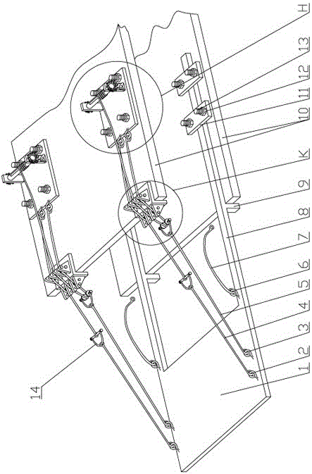
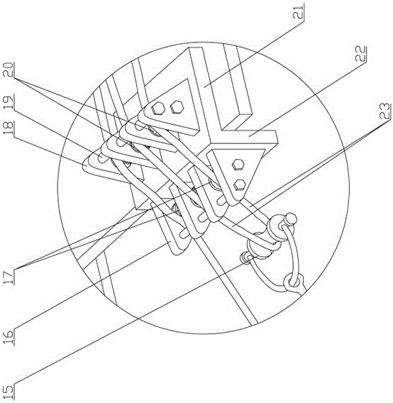
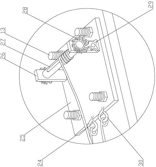
[0016] see Figure 1-Figure 3 , the present invention is a scaffold suspended material platform with a winch puller adjustment device, which has a material platform 1, and a material platform longitudinal beam 8 is provided on each side of the material platform, and each material platform longitudinal beam passes through A set of U-shaped anchor bolt fastening devices is connected to the building floor 10 slabs, and a longitudinal beam stopper 9 is provided in the middle of the bottom of each material platform longitudinal beam, and a longitudinal beam stopper 9 is provided at the symmetrical positions on both sides of the material platform. There is a group of lifting rings, and each group of lifting rings includes safety ring 2, tie ring 3 and material table lifting ring 6 in sequence, a safety wire rope 4 is connected to the safety ring, a tie wire rope 5 is connected to the tie ring, and the material table is There is a hoisting wire rope 7 connected to the hoisting ring, ...


PUM


Abstract

The invention relates to a scaffold cantilever material platform with sheave tensioning adjustment devices. The scaffold cantilever material platform comprises a material platform plate. The two sides of the material platform plate are each provided with one material platform longitudinal beam. Each material platform longitudinal beam is connected with the surface of a building floor through a U-type anchoring bolt fastening device. Two sets of hoisting rings are arranged in the symmetrical positions of the two sides of the material platform plate correspondingly. Each set of hoisting rings includes a safety hoisting ring, a tensioning hoisting ring and a material platform plate hoisting ring, wherein the safety hoisting ring is connected with a safety steel wire rope, the tensioning hoisting ring is connected with a tensioning steel wire rope, and the material platform plate hoisting ring is connected with a hoisting steel wire rope. The two sides of the upper portion of the material platform plate are each provided with one sheave tensioning adjustment device. The safety steel wire rope and the tensioning steel wire rope on the same side are jointly connected with the sheave tensioning adjustment device on the corresponding side. The tensioning force of the four steel wire ropes of the cantilever material platform in the invention is large, and safety and reliability are realized. The scaffold cantilever material platform can be repeatedly dismounted and mounted for use many times, is convenient to install, saves labor and materials when manufactured, and has remarkable economical benefits.

Description

technical field [0001] The invention relates to the technical field of building auxiliary equipment, in particular to a scaffold suspended material platform with a winch wheel tie adjusting device. Background technique [0002] Existing building cantilever material platforms are generally installed by wire rope lifting devices, which usually adopt the method of pre-embedded steel pipes, the method of lower support and diagonal support to pull up the wire rope, or the method of pre-embedded anchor rings, but they are common. The following problems: (1) The construction operation process is cumbersome, and some methods require the cooperation of welding and cutting workers to complete; (2) Most of the existing pre-embedded construction methods can only reach the force of one steel wire rope due to the restrictions on the pre-embedded position and angle. The force value of the wall and the steel wire rope is small; (3) the method of pre-embedding steel pipes in the prior art is...

Claims


Application Information

Patent Timeline
IPC IPC(8): E04G13/06E04G3/22E04G3/30
CPCE04G3/22E04G3/30E04G13/066
Inventor 张勇胜余启良安刚
Owner HUANGSHI TONGMIAO HARDWARE ELECTROMECHANICAL EQUIP CO LTD
Why Eureka
Try Eureka