
A method and system for removing heavy hydrocarbons from natural gas

A technology for natural gas and heavy hydrocarbons, applied in the field of liquefied natural gas production, can solve the problems of increased process complexity, poor separation effect, large energy consumption, etc., to improve resource utilization efficiency, increase process added value, and reduce unit energy consumption. Effect

Inactive Publication Date: 2018-09-25
BEIJING ENCRYO ENG
View PDF8 Cites 0 Cited by
  • Summary
  • Abstract
  • Description
  • Claims
  • Application Information

AI Technical Summary

Problems solved by technology

However, this method has a complicated process and consumes a lot of energy when the absorbent is regenerated.
(3) Condensation separation method: In this method, the natural gas is pre-cooled to -30~-60°C and then separated by one or more stages of heavy hydrocarbon separator. This method is not effective for the separation of aromatic hydrocarbons such as benzene, and is only suitable for the treatment of aromatic hydrocarbons. Natural gas with very low hydrocarbon content
Chinese patents CN103031169A and CN103351896A both proposed improved schemes on this basis. By setting heavy hydrocarbon scrubbers and deethanizers and / or rectification towers to separate heavy hydrocarbons, the improved schemes improved the performance of the process for removing heavy hydrocarbons, but Due to the need to add more than three separation towers, the complexity of the process is greatly increased

Method used


Image

  • A method and system for removing heavy hydrocarbons from natural gas

Examples


Embodiment 1

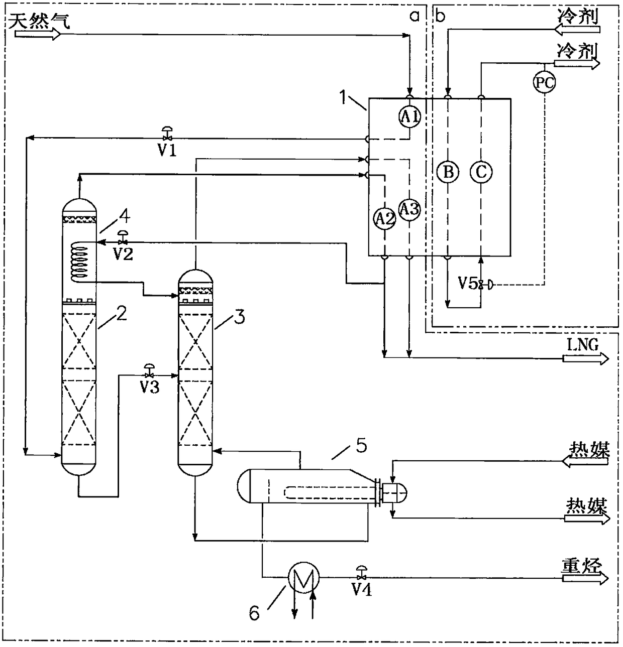
[0037] For the specific process flow of this embodiment, please refer to figure 1 .

[0038] A system for removing heavy hydrocarbons from natural gas, comprising: a first flow path A1 of a cold box 1, a second flow path A2, a third flow path A3, a demethanizer 2, a deethanizer 3, and a demethanizer condensation 4, deethanizer reboiler 5, heavy hydrocarbon cooler 6, first valve V1 to fourth valve V4 and corresponding connecting pipelines, wherein demethanizer 2 and deethanizer 3 are packed towers, and There are two sections of packing. The inlet of the first channel A1 of the cold box 1 is connected to the raw gas pipeline, and the outlet is connected to the feed port at the bottom of the demethanizer 2 through the first valve, and the feed port is located below the packing of the demethanizer 2; The inlet of the second channel A2 is connected to the shell-side gas phase outlet of the demethanizer condenser 4, and the outlet is connected to the LNG product pipeline; the inle...

Embodiment 2

[0041] For the specific process flow of this embodiment, please refer to figure 1 .

[0042] The raw natural gas I from the outside is passed into the inlet of the first channel A1 of the cold box 1. The raw natural gas is natural gas that has been deacidified, dehydrated, demercurized, and rich in heavy hydrocarbons, with a flow rate of 1265kg / h and a pressure of 6.5MPa , the temperature is -30°C, the total content of heavy hydrocarbons is 40ppmv, of which the content of neopentane is 10ppmv, the content of benzene is 10ppmv, and the content of C6 and above hydrocarbons is 20ppmv. After being cooled by the first channel A1 of the cold box 1, the temperature drops to - Natural gas II in a gas-liquid two-phase state is obtained at 80°C. The natural gas II is decompressed to 6MPa through the first valve V1 and then enters the bottom feed port of the demethanizer 2. After being purified by heavy hydrocarbon removal rectification, the temperature at the bottom of the tower is -82 ...

Embodiment 3

[0044] For the specific process flow of this embodiment, please refer to figure 1 .

[0045] The raw natural gas I from the outside is passed into the inlet of the first channel A1 of the cold box 1. The raw natural gas is natural gas that has been deacidified, dehydrated, demercurized, and rich in heavy hydrocarbons, with a flow rate of 14570kg / h and a pressure of 3.5MPa , the temperature is 35°C, the total content of heavy hydrocarbons is 10000ppmv, of which the content of neopentane is 400ppmv, the content of benzene is 600ppmv, and the content of C6 and above hydrocarbons is 9000ppmv. After being cooled by the first channel A1 of the cold box 1, the temperature drops to -45 ℃ to obtain natural gas II in a gas-liquid two-phase state. The natural gas II is decompressed to 3.4MPa through the first valve V1 and then enters the bottom feed port of the demethanizer 2. After heavy hydrocarbon removal and rectification purification, the temperature at the bottom of the tower is -4...


PUM


Abstract

The invention relates to a method and system for removing heavy hydrocarbon from natural gas.The method comprises the steps that firstly, natural gas is cooled through a cooling box (1) and then fed into a demethanizing column (2) for rectification to separate heavy hydrocarbon, a gas phase obtained after rectification separation enters a demethanizing column condenser (4) and is partially condensed in the demethanizing column condenser (4), a condensed liquid phase returns to the demethanizing column (2), and the uncondensed gas phase returns to the cooling box (1) to be further deeply cooled to obtain an LNG product I; the liquid phase led out of the bottom of the demethanizing column (2) is decompressed and then fed into a dethanizing column (3) to be rectified again for further separation; gas phase flow at the top of the dethanizing column (3) returns to the cooling box (1) to be further deeply cooled after meeting the deep cooling requirement to obtain an LNG product II; the separated liquid phase is led out of a liquid phase outlet of a reboiler (5) at the bottom of the dethanizing column, is cooled with a heavy hydrocarbon cooler (6) and decompressed, and a heavy hydrocarbon product is obtained.According to the method, a strand of the LNG product I at an outlet of the cooling box (1) is extracted to provide cold capacity for the heavy hydrocarbon removing process, the heavy hydrocarbon removing process is coupled in the natural gas liquefaction process, the process integration level is high, and the method is good in stability, high in applicability and very high in operability.

Description

technical field [0001] The invention relates to the field of liquefied natural gas production, in particular to a method and system for removing heavy hydrocarbons from natural gas. Background technique [0002] In the field of liquefied natural gas, heavy hydrocarbons usually refer to C5 and above hydrocarbons. Since the boiling point of hydrocarbons varies from low to high as the molecular weight increases from small to large, heavy hydrocarbons are always condensed first in the process of liquefying natural gas. If heavy hydrocarbons are not separated in advance, there will be a risk of heavy hydrocarbons freezing and blocking equipment during the cryogenic process of natural gas. In order to ensure the normal operation of the natural gas liquefaction system, especially the cold box, measures must be taken to remove heavy hydrocarbons from the natural gas before it enters the cold box or the cryogenic section of the cold box. [0003] At present, the methods for removin...

Claims


Application Information

Patent Timeline
Patent Type & Authority Patents(China)
IPC IPC(8): C10L3/10
CPCC10L3/10C10L3/101C10L2290/543
Inventor 张会军王道广李慧王英军
Owner BEIJING ENCRYO ENG
Learn More