Thermoplastic composite material joint connecting method

A composite material and joint connection technology, applied in the field of thermoplastic composite material repair, can solve the problems of short service life, difficulty in repairing damage, weak mechanical properties of connecting parts, etc., to improve mechanical properties and reliability, reduce environmental sensitivity, reduce The effect of practical risk

Inactive Publication Date: 2016-07-06
CIVIL AVIATION UNIV OF CHINA
View PDF5 Cites 7 Cited by
  • Summary
  • Abstract
  • Description
  • Claims
  • Application Information

AI Technical Summary

Problems solved by technology

However, due to its manufacturing process and its use characteristics, thermoplastic composite materials will inevitably involve joint connection problems in the process of manufacturing and repairing.
At present, the mechanical or adhesive method is usually used. Although the mechanical method is relatively simple, the process performance is relatively stable, and it is not affected by the construction environment, the disadvantage is that serious stress concentration will occur at the nail hole during screw connection, which will cause damage to the original structure. , and there will be corrosion problems of fasteners, so the mechanical properties of the connection parts are weak, resulting in a relatively short service life, and it will also cause greater difficulty in damage repairs, such as deformation of the connection joints, insufficient strength of re-drilling, etc. problems, so usually used as a temporary connection method to meet emergencies
Adhesive bonding methods mainly include patching and butt jointing. Although the structure of adhesive bonding has a long service life and can usually be used permanently, however, the equipment required for this connection method is complicated, and it is necessary to rely on the adhesive layer to transfer the patch and the connected material. Loading between composite structures, therefore low reliability, environmental sensitivity, and bondline damage is not easy to detect

Method used


Image

  • Thermoplastic composite material joint connecting method
  • Thermoplastic composite material joint connecting method
  • Thermoplastic composite material joint connecting method

Examples


Embodiment Construction

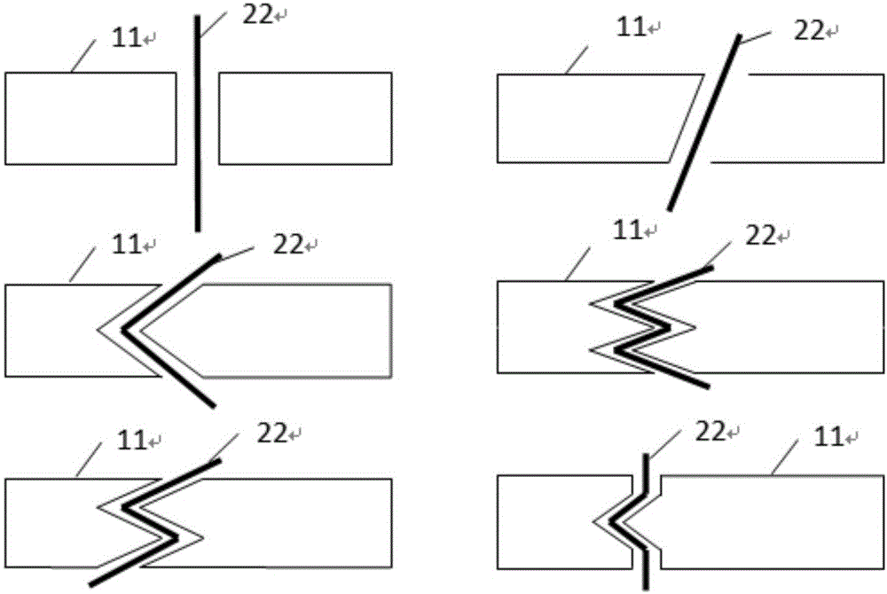
[0019] The method for connecting thermoplastic composite joints provided by the present invention will be described in detail below in conjunction with specific embodiments.

[0020] Such as figure 1 — Figure 4 As shown, the thermoplastic composite material joint connection method provided by the present invention includes the following steps carried out in order:

[0021] 1) Pretreating the joints of the two thermoplastic composite materials 11 to be connected; the pretreatment method is to first polish the joints, then clean them with absolute ethanol and dry them;

[0022] 2) Fix the above-mentioned thermoplastic composite material 11 on the fixture in such a way that the joints are opposite or overlapping, pay attention to the force exerted by the fixture so that the thermoplastic composite material 11 cannot be deformed or damaged, and ensure that the thermoplastic composite material 11 is connected during the welding process intact;

[0023] 3) Clamp the carbon fiber...


PUM


Abstract

A method for connecting joints of thermoplastic composite materials, which includes pretreating the joint parts of thermoplastic composite materials; fixing the thermoplastic composite materials on a fixture in a way that the joint parts are opposite or overlapping; clamping carbon fiber unidirectional tapes or fabrics on the thermoplastic composite materials Between the joints, leave some carbon fiber unidirectional tape or fabric outside the joints, apply conductive glue and clamp it on the conductive clip of the heating equipment, turn on the DC power supply of the heating equipment, until the joints are welded together to form a joint ; Steps such as trimming the shape of the joint. Effects of the present invention: the joint structure made has less influence on the in-plane performance of thermoplastic composite materials, lowers environmental sensitivity, less weight gain to the structure, less change in shape, and can improve the bonding effect between joints of thermoplastic composite materials , so that the mechanical properties and reliability of the thermoplastic composite joint structure can be improved, and the practical risk of the thermoplastic composite joint structure can be reduced.

Description

technical field [0001] The invention belongs to the technical field of repairing thermoplastic composite materials, and in particular relates to a joint connection method of thermoplastic composite materials. Background technique [0002] With the development of composite materials, thermoplastic composite materials have been widely used in aerospace aircraft, Military fields such as missiles, rockets, and artificial satellites, as well as civilian fields such as racing cars, ships, high-speed trains, bridges, and wind power blades. However, due to its manufacturing process and its use characteristics, thermoplastic composite materials will inevitably involve joint connection problems in the process of manufacturing and repairing. At present, the mechanical or adhesive method is usually used. Although the mechanical method is relatively simple, the process performance is relatively stable, and it is not affected by the construction environment, the disadvantage is that seri...

Claims


Application Information

Patent Timeline
IPC IPC(8): B29C65/30
CPCB29C65/30B29C66/02245B29C66/3024
Inventor 王志平纪朝辉王宏洋
Owner CIVIL AVIATION UNIV OF CHINA
Why Eureka
Try Eureka