Flue gas mercury removal method based on visible light and its ring spray mercury removal device

A visible light and mercury removal technology, applied in the field of environmental pollution prevention and control, can solve the problems of increasing the commercial value of fly ash, large flue gas flow resistance, and insignificant removal effect, so as to improve flue gas purification efficiency, reduce costs, and reduce smoke Effect of air purification cost

Active Publication Date: 2018-12-04
HENAN POLYTECHNIC UNIV
View PDF3 Cites 1 Cited by
  • Summary
  • Abstract
  • Description
  • Claims
  • Application Information

AI Technical Summary

Problems solved by technology

The fixed-bed adsorption mercury removal device needs to install a special adsorption bed, which has the disadvantage of large flue gas flow resistance; the use of spray technology mercury removal device will increase the commercial value of fly ash; conventional pollutant removal equipment has a great impact on Hg 0 The removal effect is not obvious
Generally, the mercury removal efficiency of fixed-bed adsorption mercury removal devices and spray technology mercury removal devices is low. Although the mercury removal efficiency can be improved by using modified adsorbents, the operating costs will increase significantly.

Method used


Image

  • Flue gas mercury removal method based on visible light and its ring spray mercury removal device
  • Flue gas mercury removal method based on visible light and its ring spray mercury removal device
  • Flue gas mercury removal method based on visible light and its ring spray mercury removal device

Examples


Embodiment 1

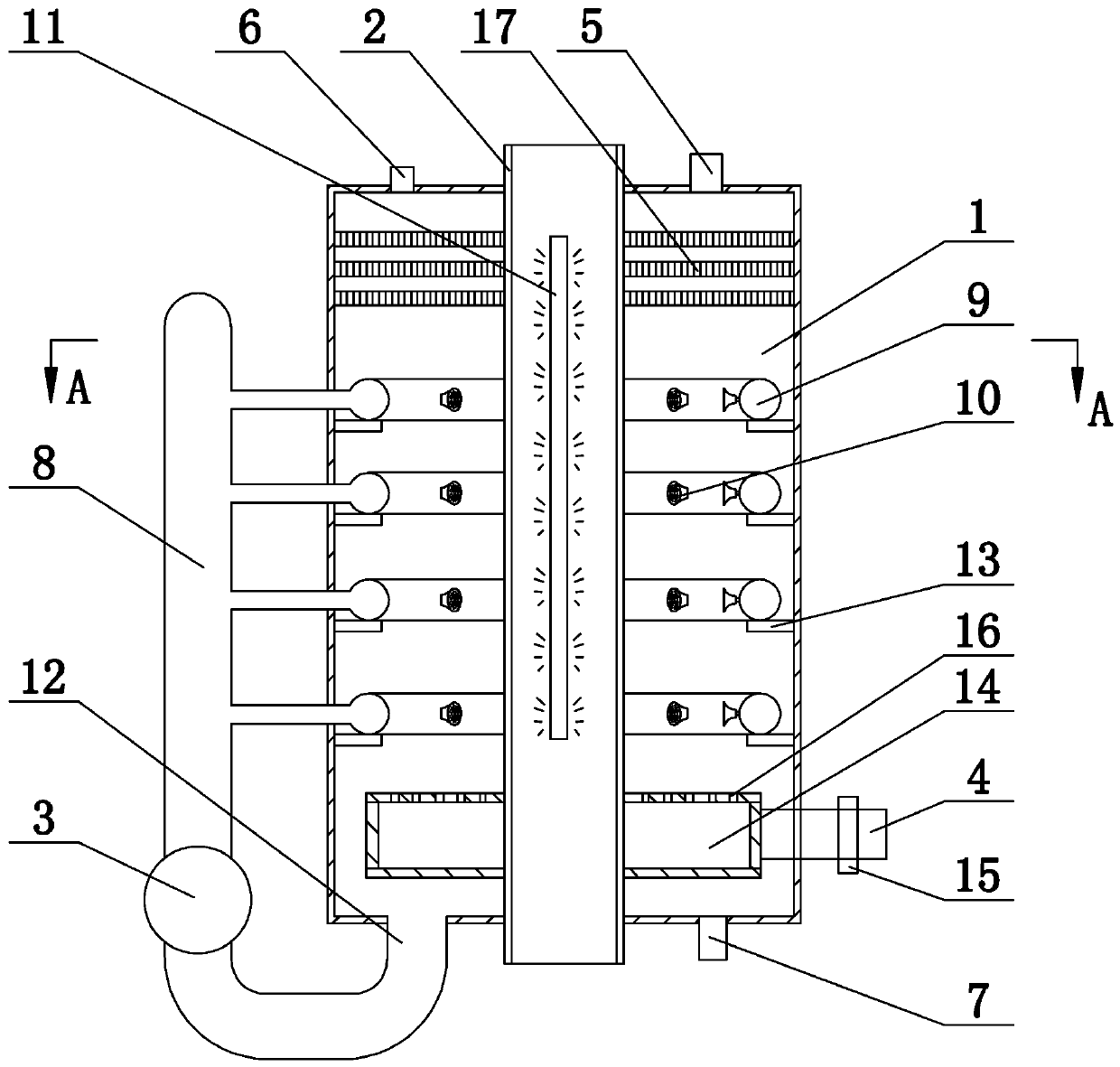
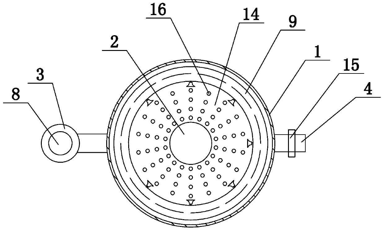
[0040] like figure 1 , figure 2 As shown, a ring spray mercury removal device for flue gas mercury removal based on visible light includes a reactor 1, a central quartz glass tube 2, a circulation pump 3, an air intake pipe 4, an exhaust port 5, a liquid inlet 6, Liquid discharge port 7, circulation pipe 8, ring nozzle pipe 9 and sprinkler head 10, the bottom of the reactor 1 is connected to the inlet pipe 4, the bottom of the reactor 1 is provided with an air distribution box 14, and the air distribution box 14 is connected to the inlet pipe 4 to enter A one-way valve 15 is arranged on the air pipe 4, and an air distribution hole 16 is evenly arranged on the top plate of the air distribution box 14, and the central quartz glass tube 2 is installed in the reactor 1, and the central quartz glass tube 2 is connected with the reaction vessel. The reactor 1 is sealed and tightly connected, the central quartz glass tube 2 is provided with a visible light source 11, the reactor 1 ...

Embodiment 2

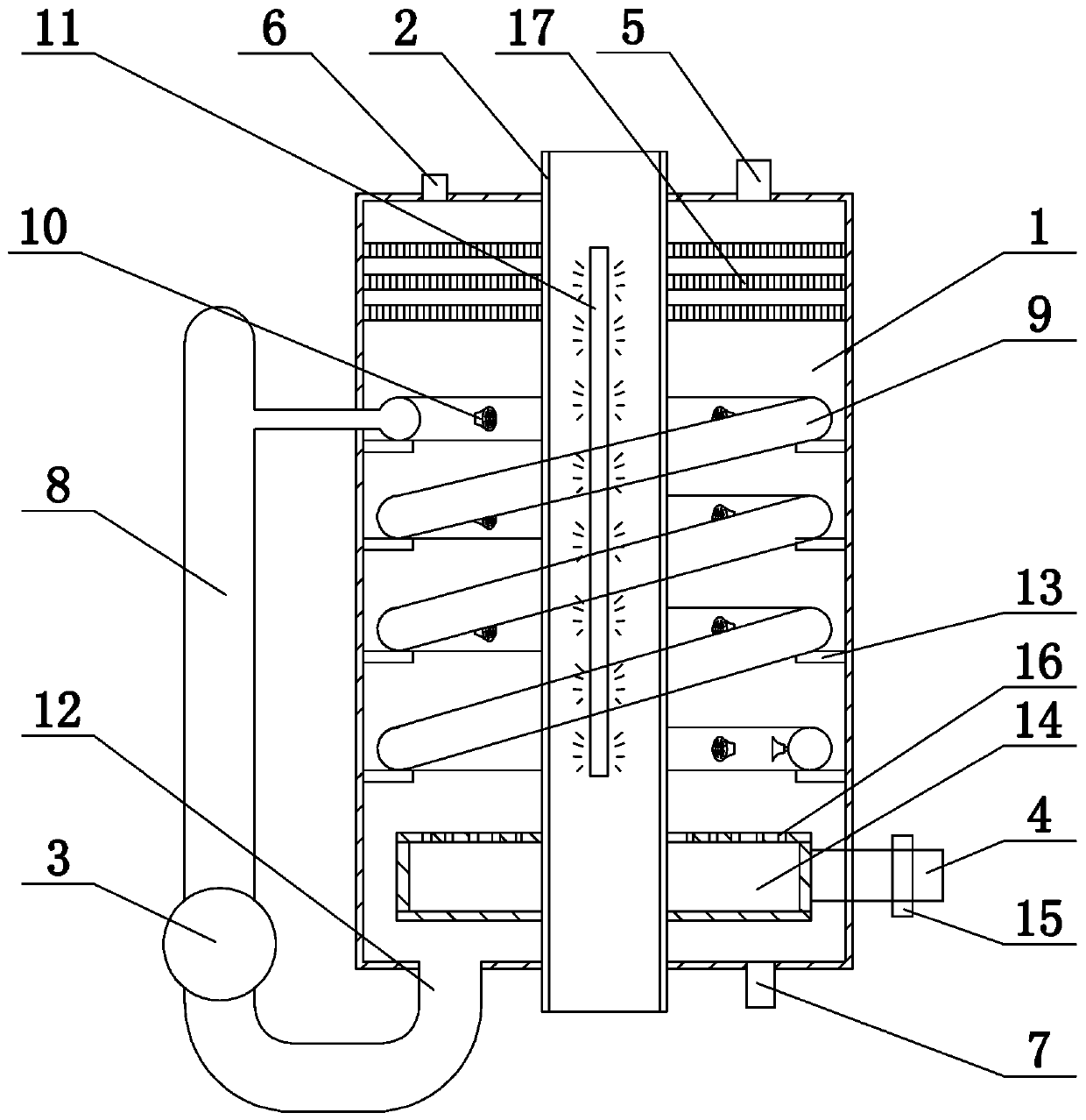
[0064] like image 3 As shown, repeating Example 1, there are the following differences, the ring nozzle 9 is centered on the central quartz glass tube 2 and spirally wound on the inner wall of the reactor 1 from top to bottom, and the ring nozzle 9 is evenly arranged with multiple 10 sprinkler heads. The inner wall of the reactor 1 is spirally provided with a support plate 13 , the ring nozzle 9 is placed on the support plate 13 , and the support plate 13 supports the ring nozzle 9 .

[0065] This embodiment adopts composite catalyst The method for removing mercury from coal-fired flue gas is as follows:

[0066] 1. Catalyst preparation

[0067]1) Add 50-350 ml of glacial acetic acid into 0-300 ml of deionized water, stir evenly for 10-30 minutes, add 0.16 mol of KI, stir magnetically for 20-60 minutes, add 0.08 mol of bismuth nitrate and 0.08 mol of silver nitrate to obtain the catalyst Solution, denoted as A solution;

[0068] 2) Add 50-350 ml of glacial acetic acid...

Embodiment 3

[0082] Repeat Example 1, with the following differences:

[0083] This embodiment adopts composite catalyst The method for removing mercury from coal-fired flue gas is as follows:

[0084] 1. Catalyst preparation

[0085] 1) Add 50-350 ml of glacial acetic acid into 0-300 ml of deionized water, stir evenly for 10-30 minutes, add 0.18 mol of KI, stir magnetically for 20-60 minutes, add 0.09 mol of bismuth nitrate and 0.09 mol of silver nitrate to obtain the catalyst Solution, denoted as A solution;

[0086] 2) Add 50-350 ml of glacial acetic acid into 0-300 ml of deionized water, stir evenly for 10-30 minutes, add 0.02 mol of KBr, stir magnetically for 20-60 minutes, add 0.01 mol of bismuth nitrate and 0.01 mol of silver nitrate to obtain visible light catalyst Solution, denoted as B solution;

[0087] 3) Under magnetic stirring, mix solution B with solution A, stir magnetically for 20 to 60 minutes, let it stand for 5 to 10 hours, then place it under a 60 to 150 watt ...


PUM


Abstract

The invention provides a visible light-based flue gas mercury removal method and a circular spraying-type mercury removal device employing the same. A reaction liquid containing a compound catalyst Ag / AgBr<1-x>I<x>-BiOBr<1-x>I<x> (x=0.6-1) is irradiated by a visible light and then releases hydroxyl radical.OH, superoxide anion radical.O2<-> and holes h<+>; the hydroxyl radical .OH, the superoxide anion radical .O2<-> and the holes h<+> have high oxidizing property; Hg<0> in the flue gas can be oxidized into Hg<2+>, so that the Hg<0> is removed in a form of the Hg<2+>, and the target of flue gas mercury removal is achieved. The mercury removal device is a circular spraying-type mercury removal device; the mercury flue gas enters from the lower part of a reactor and flows from bottom to top; a visible light source is arranged in a central quartz glass tube at the middle part of the reactor; circular spraying pipes are circularly arranged employing the central quartz glass tube as the center; the reaction liquid is sprayed towards the central quartz glass tube from the circular spraying pipes, namely the reaction liquid is sprayed from the outside to the inside; and the flue gas from which mercury is removed is discharged from a gas outlet in the top end of the reactor.

Description

Technical field: [0001] The invention belongs to the technical field of environmental pollution prevention and control, and in particular relates to a method for removing mercury from flue gas based on visible light and a ring spray type mercury removing device. Background technique: [0002] The "Emission Standards of Air Pollutants for Thermal Power Plants" (GBl3223-2011) implemented on January 1, 2012 clearly stipulated the emission requirements of mercury for the first time, that is, since January 1, 2015, the emission of mercury and its compounds is limited to 0.03 mg / m 3 . Subsequently, the "Twelfth Five-Year Plan for the Prevention and Control of Air Pollution in Key Regions" issued by my country also proposed to carry out the prevention and control of atmospheric mercury emission pollution, further develop the pilot project of monitoring and control of atmospheric mercury emission, actively promote the coordinated control of mercury emission, and compile coal-fired,...

Claims


Application Information

Patent Timeline
Patent Type & Authority Patents(China)
IPC IPC(8): B01D53/86B01D53/64B01J27/06B05B1/18
CPCB01D53/8665B01D2251/10B01D2255/802B01D2257/602B01D2258/0283B01J27/06B05B1/18
Inventor 张安超邢微波张丹李成伟陈小砖盛伟刘志超
Owner HENAN POLYTECHNIC UNIV
Why Eureka
Try Eureka