an accelerator tube

A technology of accelerating tube and accelerating cavity, which is applied in the field of accelerating tube, can solve the problems of limited adjustment range, weakened beam-forming effect, and poor capture rate of beam current at the exit of accelerating tube, and achieves stable operation and small frequency disturbance. Effect

Active Publication Date: 2021-03-16
SHANGHAI UNITED IMAGING HEALTHCARE
View PDF8 Cites 0 Cited by
  • Summary
  • Abstract
  • Description
  • Claims
  • Application Information

AI Technical Summary

Problems solved by technology

Usually an accelerator only works optimally at one acceleration energy. When multiple levels of energy are required, the size of the microwave entering the acceleration tube needs to be changed. However, this method has its own disadvantages: the electron linear acceleration tube includes a beamforming section and a speed of light section, the quality of the beam at the outlet of the accelerating tube is mainly determined by the focusing effect of the focusing section. When the accelerating tube is designed, the focusing section will be optimized so that the beamforming effect is the best at a certain energy; when the microwave When the power is changed, the amplitude of the electric field in the beamforming section will also change, resulting in a change in the optimal beamforming conditions, weakening of the beamforming effect, and deterioration of the energy dissipation and capture rate of the beam at the exit of the accelerating tube.
[0004] However, the energy switches of the prior art are either structurally too complex or have a limited adjustment range

Method used


Image

  • an accelerator tube
  • an accelerator tube
  • an accelerator tube

Examples


Embodiment Construction

[0026] In order to make the above objects, features and advantages of the present invention more clearly understood, the specific embodiments of the present invention will be described in detail below with reference to the accompanying drawings.

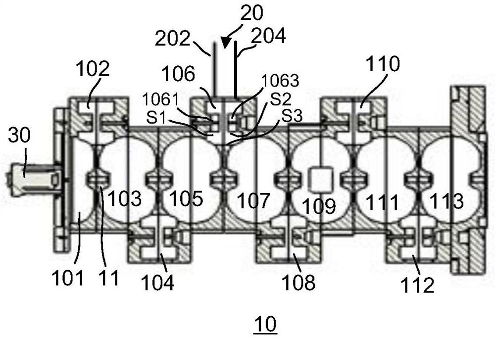
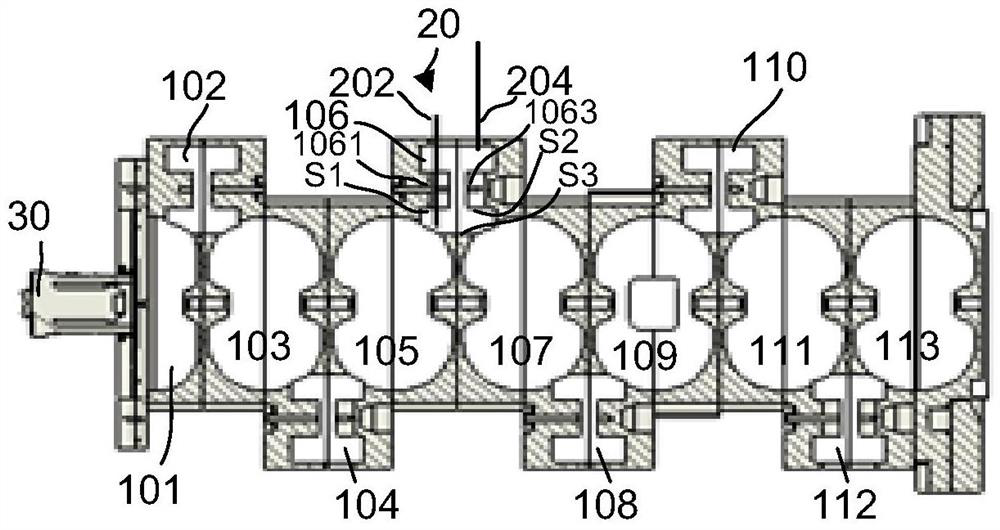
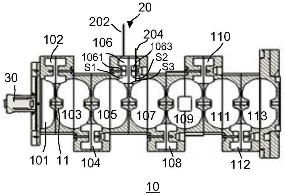
[0027] like Figure 1-Figure 3 shown, according to one embodiment of the present invention, figure 1 is a schematic diagram of the structure of the accelerating tube when it is in the first mode, figure 2 is a schematic diagram of the structure of the accelerating tube when it is in the second mode, image 3 It is a schematic diagram of the structure of the accelerating tube when it is in the third mode.

[0028]Specifically, the accelerating tube 10 is a standing wave accelerating tube. One end of the accelerating tube 10 may be coupled to an electron gun 30 that generates an electron beam, and the other end of the accelerating tube 10 may be coupled to a target assembly such that the electron beam emitted from the accelerating ...


PUM


Abstract

An accelerating tube includes at least two adjacent accelerating cavities and side coupling cavities coupled to the two adjacent accelerating cavities, the side coupling cavities are provided with a switch assembly, the switch assembly includes an insert, The insert is arranged along a direction substantially perpendicular to the beam path and is offset from a central axis of the side coupling cavity substantially perpendicular to the beam path, the switch assembly is between a first state and a second state The interval is adjustable; wherein, in the first state, the insert is not inserted into the side coupling cavity; in the second state, the insert is inserted into the side coupling cavity so that Its end is adjacent to the coupling hole formed by the side coupling cavity and the accelerating cavity.

Description

technical field [0001] The invention relates to the field of medical equipment, in particular to an acceleration tube. Background technique [0002] Medical electron linear accelerators use microwaves to accelerate electrons to a certain energy, and bombard metal targets to generate X-rays. Usually an accelerator only works optimally at one acceleration energy. When multiple energies are required, the size of the microwaves entering the accelerator tube needs to be changed. However, this method has its own drawbacks: the electron linear accelerator tube includes a bunching section and the speed of light. The quality of the beam at the exit of the accelerating tube is mainly determined by the bunching effect of the bunching section. When the accelerating tube is designed, the bunching section will be optimized, so that at a certain energy, the bunching effect is the best; when the microwave When the power is changed, the amplitude of the electric field of the bunching sectio...

Claims


Application Information

Patent Timeline
Patent Type & Authority Patents(China)
IPC IPC(8): H05H9/04
CPCH05H9/04H05H2277/10
Inventor 廖浪宋瑞英倪成
Owner SHANGHAI UNITED IMAGING HEALTHCARE
Why Eureka
Try Eureka