
Urban rail vehicle auxiliary power supply system and method

An urban rail vehicle and power supply system technology, applied in the field of urban rail vehicles, can solve the problems of reducing the ride comfort of the vehicle, uneven temperature in the passenger room, and low energy utilization efficiency of the train, so as to reduce the workload of operation and maintenance, and solve the problem of the temperature of the passenger room. Non-uniformity, the effect of improving energy efficiency

Active Publication Date: 2016-06-29
ZHUZHOU ELECTRIC LOCOMOTIVE CO
View PDF4 Cites 2 Cited by
  • Summary
  • Abstract
  • Description
  • Claims
  • Application Information

AI Technical Summary

Problems solved by technology

[0002] The existing auxiliary power supply system of urban rail vehicles adopts a fixed-load power supply scheme. When all auxiliary inverters of the train are working normally, all load equipment such as air-conditioning units are continuously turned on at the same time. The output power of the train is too low, resulting in low energy utilization efficiency of the train
When some auxiliary inverters fail, the auxiliary power supply system cuts off the air-conditioning unit fixedly through the hard-wire circuit to solve the problem of insufficient capacity of the auxiliary power supply system. This fixed cut-off scheme will make the temperature of the passenger compartment uneven and reduce the comfort of the vehicle. In addition, it is necessary to manually set and adjust the temperature of the air conditioner in the passenger room according to the weather changes, and the workload of operation and maintenance is heavy.

Method used


Image

  • Urban rail vehicle auxiliary power supply system and method
  • Urban rail vehicle auxiliary power supply system and method
  • Urban rail vehicle auxiliary power supply system and method

Examples


Embodiment Construction

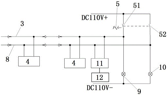
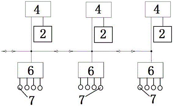
[0026] Such as Figure 1 to Figure 3 As shown, an embodiment of the auxiliary power supply system of the present invention includes a K-section passenger room, an auxiliary inverter 2 connected to the air-conditioning unit 1 in each section of the passenger room, the auxiliary inverter 2 is connected to the air-conditioning unit 1, and the air-conditioning Unit 1 is equipped with several air-conditioning compressors, and also includes the first MVB communication train line 3, VCU4 and control switch 5 in each cab, VCU4 is set in the relay cabinet in the cab, and control switch 5 is set in the driver's cab On the platform; the intelligent air-conditioning controller 6 and 4 temperature sensors 7 in each passenger room; the 4 temperature sensors 7 are connected to the intelligent air-conditioning controller 6 in the passenger room, and the control switch 5 includes a first switch 51, so Both ends of the first switch 51 are connected to the first MVB communication train line 3, t...


PUM


Abstract

The invention discloses an urban rail vehicle auxiliary power supply system and method.The urban rail vehicle auxiliary power supply system comprises an auxiliary inverter inside each passenger room and connected with an air-conditioner unit.A plurality of air-conditioner compressors are arranged inside the air-conditioner unit.The urban rail vehicle auxiliary power supply system further comprises a first MVB communication train line, a VCU and a control switch inside each driver room, an intelligent air-conditioner controller inside each passenger room and X temperature sensors.The X temperature sensors are connected with the intelligent air-conditioner controllers of the corresponding passenger rooms.The control switch comprises a first switch.The two ends of the first switch are connected to the first MVB communication train line.The VCUs are connected with the first MVB communication train line.The auxiliary inverters and the intelligent air-conditioner controllers are connected with the VCUs.The power of the whole-train air-conditioner unit is dynamically adjusted, the output power of the auxiliary power supply system can be automatically adjusted according to the environment temperature, the energy utilization efficiency is greatly improved, the riding comfort is improved, and operation and maintenance workloads of drivers are lowered.

Description

technical field [0001] The invention belongs to the field of urban rail vehicles, in particular to an auxiliary power supply system and method for urban rail vehicles. Background technique [0002] The existing auxiliary power supply system of urban rail vehicles adopts a fixed-load power supply scheme. When all auxiliary inverters of the train are working normally, all load equipment such as air-conditioning units are continuously turned on at the same time. The output power of the train is too low, resulting in low energy utilization efficiency of the train. When some auxiliary inverters fail, the auxiliary power supply system cuts off the air-conditioning unit fixedly through the hard-wire circuit to solve the problem of insufficient capacity of the auxiliary power supply system. This fixed cut-off scheme will make the temperature of the passenger compartment uneven and reduce the comfort of the vehicle. In addition, it is necessary to manually set and adjust the tempera...

Claims


Application Information

Patent Timeline
Patent Type & Authority Applications(China)
IPC IPC(8): B60L1/04B61D27/00
CPCB60L1/04B60L2200/26B61D27/0018Y02T10/72Y02T30/00Y02T90/16
Inventor 曹增明周利彭驹吴桂林梁波
Owner ZHUZHOU ELECTRIC LOCOMOTIVE CO
Learn More