
A new color-changing valve structure and its working method

A new type of paint technology, applied in the field of color change valves, can solve the problems of increasing solvent consumption and achieve the effect of reducing color change time and saving solvent consumption

Active Publication Date: 2019-02-22
SHANGHAI FANUC ROBOTICS
View PDF7 Cites 0 Cited by
  • Summary
  • Abstract
  • Description
  • Claims
  • Application Information

AI Technical Summary

Problems solved by technology

[0003] In order to solve the problem that the traditional color change valve needs to clean the main pipeline of the color change valve every time the color is changed, which increases the consumption of solvent, the present invention provides a new color change valve structure and its working method

Method used


Image

  • A new color-changing valve structure and its working method

Examples


Embodiment

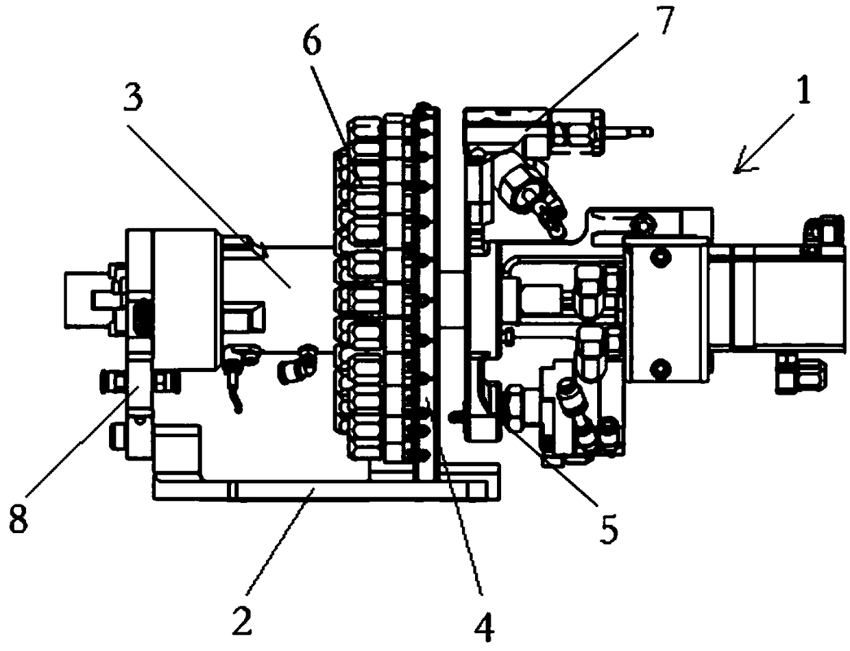
[0020] See figure 1 As shown, the structure of a novel color-changing valve 1 of the present invention includes a base 2, a main shaft 3, a wheel 4 and a turntable 5, wherein the main shaft 3 is horizontally arranged above the base 2 and runs through the wheel 4, and the turntable 4 is rotatable The ground is connected with the main shaft 3, the wheel disc 4 has a number of paint input ports 6, and the turntable 5 has a paint output port 7, the paint input port 6 and the paint output port 7 can be docked to realize the replacement of spray paint and paint color.

[0021] On the basis of the above, the present invention also has the following implementation modes, please continue to refer to figure 1 as shown,

[0022] In a further embodiment of the present invention, several paint input ports 6 are uniformly arranged on the edge of the wheel 4 .

[0023] In a further embodiment of the present invention, the paint output port 7 is arranged on the edge of the turntable 5, and ...


PUM


Abstract

The invention discloses a novel color changing valve structure and a work method thereof. The novel color changing valve structure comprises a base, a spindle, a wheel disc and a rotating disc; the spindle is horizontally arranged above the base and penetrates the wheel disc, and the rotating disc is rotatably connected with the spindle; the wheel disc is provided with a plurality of coating input openings, and a coat output opening is formed in the rotating disc; and the process that in the color changing process of a traditional color changing valve, a color changing valve main pipeline needs to be cleaned is omitted. According to a color changing valve, the color changing time can be shortened, and meanwhile solvent consumption can be further saved.

Description

technical field [0001] The invention relates to the technical field of color changing valves, in particular to a novel color changing valve structure and working method thereof. Background technique [0002] The traditional color-changing valve adopts modular color-changing valve groups to splice together to realize the switching of multiple colors. According to the number of different colors, different numbers of color-changing modules are spliced. The traditional color-changing valve uses a pneumatic valve to control the closing or conducting of the paint. After the pneumatic valve of a certain color paint is turned on, it will flow out through the main pipeline in the middle of the color change valve group. Every time the color is changed, the traditional color change valve needs to use solvent to clean the main pipe, so that another color paint can flow out through the main pipe. The traditional color change valve needs to use solvent to clean the main pipe of the color...

Claims


Application Information

Patent Timeline
Patent Type & Authority Patents(China)
IPC IPC(8): B05B12/14
CPCB05B12/149
Inventor 姚炜沈为召刘玉龙董德权袁华雷徐文君顾玉兴徐磊毛照友
Owner SHANGHAI FANUC ROBOTICS
Learn More