
Low-power consumption and accurate sleep timer circuit and method

A low-power, timer technology, applied in electrical components, electronic switches, pulse technology, etc., can solve the problems of processor power consumption, inaccuracy of sleep timing, etc., to improve reliability, reduce processor resource overhead, simple structure

Active Publication Date: 2016-06-22
SHENYANG INST OF AUTOMATION - CHINESE ACAD OF SCI
View PDF4 Cites 14 Cited by
  • Summary
  • Abstract
  • Description
  • Claims
  • Application Information

AI Technical Summary

Problems solved by technology

This method solves the problem of power consumption and precision to a certain extent, but it is still not ideal for the following reasons: the participation of the processor will still generate unnecessary power consumption; the non-determinism of processor wake-up leads to sleep timing imprecision

Method used


Image

  • Low-power consumption and accurate sleep timer circuit and method
  • Low-power consumption and accurate sleep timer circuit and method
  • Low-power consumption and accurate sleep timer circuit and method

Examples


Embodiment

[0149] This embodiment is a way to realize the clock state indication circuit described in this patent, and adopts a relatively simple circuit structure, wherein the value of N in the clock frequency division circuit is 2, that is, adopts 2-equal duty frequency division, shifting The bit register uses a 3-bit register shift register circuit.

[0150] For specific examples, please refer to Figure 4 As shown, a clock state indicating circuit structurally includes a clock frequency division circuit, an edge detection circuit, an edge correction circuit and a shift register circuit; the external port includes an output port reference clock and a clock to be tested, and the output port clock state.

[0151] The specific connection relationship is that the reference clock signal is connected to the clock port CK of the clock frequency division circuit, and the clock output port Q of the clock frequency division circuit generates a frequency-divided clock signal C1; the clock signal...


PUM


Abstract

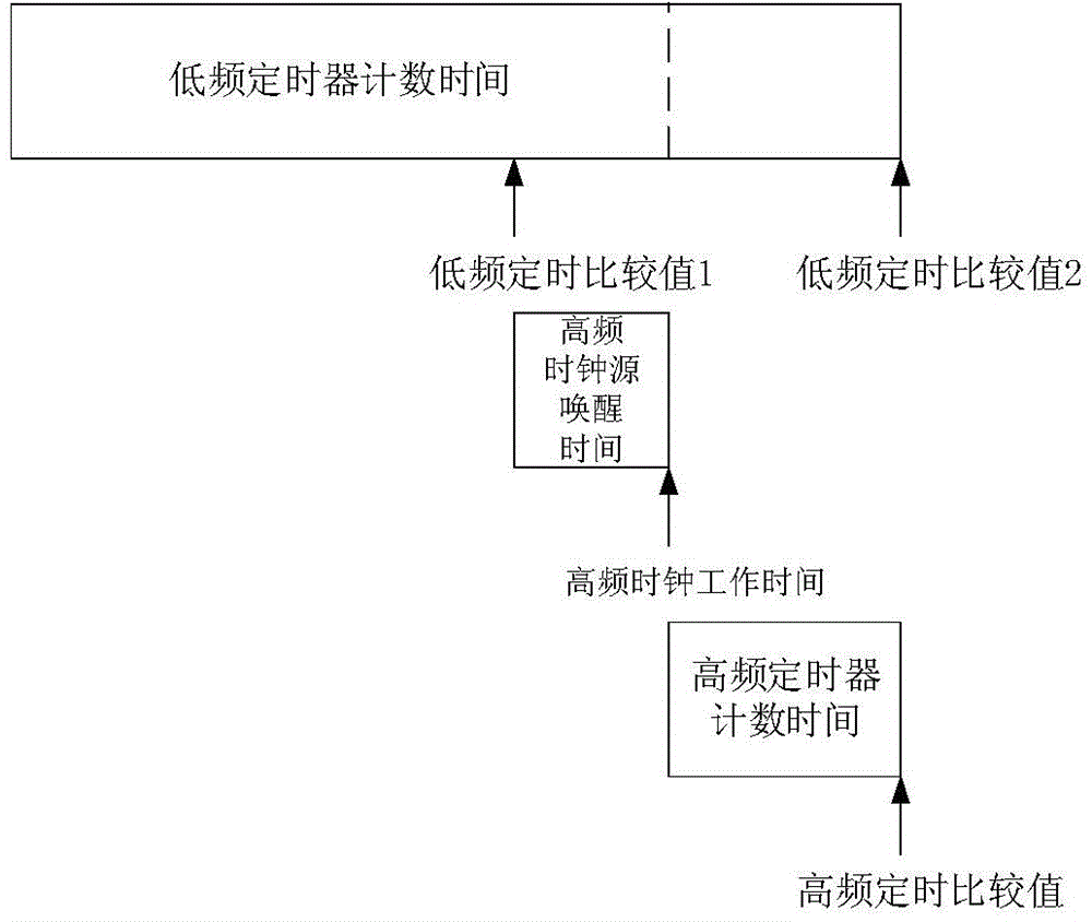
The invention relates to a low-power consumption and accurate sleep timer circuit. The low-power consumption and accurate sleep timer includes a high-frequency clock source, a low-frequency clock source, a clock state indicating circuit, a control circuit, timers, a high-frequency timing margin calculator, a low-frequency timing margin calculator, comparators and a timer result decision device. According to a low-power consumption and accurate sleep timing method, sleep timing is completed by means of automatic switching of two timers. According to the circuit of the invention, circuit structures such as the high-frequency clock source, the low-frequency clock source, the clock state indicating circuit, the control circuit, the high-frequency timing margin calculator and the low-frequency timing margin calculator are adopted; and according to the method, hardware is utilized to control the high-frequency timing margin calculator and the low-frequency timing margin calculator. With the circuit and method adopted, a detect that switching is carried out by means of a processor in the prior art can be eliminated, the resource overhead of the processor can be decreased, timing accuracy can be improved, and power consumption of a system can be decreased.

Description

technical field [0001] The invention relates to a dormancy timer circuit and method with low power consumption and precision, in particular to a system-on-chip chip-oriented dormancy timer circuit and method which can effectively reduce power consumption and provide precise timing. Background technique [0002] Timing issues are a very common problem in embedded systems. Different embedded processors contain different timing units, and different system applications require different timing applications. Common timer types include general timers, input pulse length timers, output pulse timers, multiple input / output timers, and timers combined with functional modules. There are more types of timers for applications, such as sending timers, receiving timers, sleep timers, and real-time clock timers. [0003] A sleep timer is a type of timer. The working principle of the ideal sleep timer is generally to set a timing time before the system sleeps, and it is started during sle...

Claims


Application Information

Patent Timeline
Patent Type & Authority Applications(China)
IPC IPC(8): H03K17/28H03K17/22
Inventor 谢闯董策段茂强张志鹏杨志家王剑崔书平
Owner SHENYANG INST OF AUTOMATION - CHINESE ACAD OF SCI
Learn More