Eureka AIR delivers breakthrough ideas for toughest innovation challenges, trusted by R&D personnel around the world.

Multi-wavelength tunable laser based on polarization-maintaining chirped phase-shift fiber grating

A technology of phase-shifting fiber grating and chirped fiber grating, which is applied in the field of optical fiber communication and instrumentation, and can solve the problems of high cost and high cost of laser system

Inactive Publication Date: 2016-06-22
BEIJING JIAOTONG UNIV
View PDF3 Cites 5 Cited by
  • Summary
  • Abstract
  • Description
  • Claims
  • Application Information

AI Technical Summary

Problems solved by technology

Scheme 8 uses the Brillouin scattering effect in the fiber to obtain multi-wavelength laser output, but the Brillouin effect needs to be pumped by a tunable semiconductor distributed feedback laser to produce it, resulting in a higher cost for the entire laser system
Solution 9 is to use fiber Raman amplifiers, semiconductor optical amplifiers, or erbium-doped fiber amplifiers and semiconductor optical amplifiers with mixed gain to obtain multi-wavelength lasers with balanced power and stable output, but the cost is relatively high

Method used


Image

  • Multi-wavelength tunable laser based on polarization-maintaining chirped phase-shift fiber grating
  • Multi-wavelength tunable laser based on polarization-maintaining chirped phase-shift fiber grating
  • Multi-wavelength tunable laser based on polarization-maintaining chirped phase-shift fiber grating

Examples


Embodiment 1

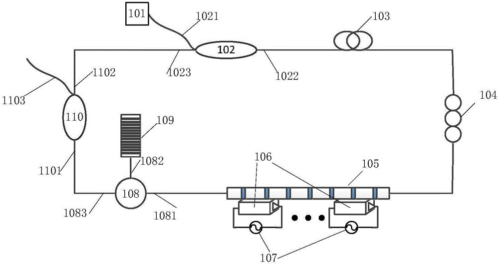
[0027] The laser includes a pumping light source 101, a wavelength division multiplexer 102, a doped fiber 103 with a length of 2 meters, a polarization controller 104, a polarization-maintaining chirped fiber grating 105, a piezoelectric ceramic 106, an electrical signal generator 107, and an optical ring. shaper 108, polarization maintaining uniform fiber grating 109, fiber 90:10 coupler 110. The specific link method is:

[0028] The pump light source 101 is connected to the first port 1021 on the left side of the wavelength division multiplexer 102, and the port 1022 on the right side of the wavelength division multiplexer 102 is connected to one end of a doped optical fiber 103 with a length of 2 meters. The other end of the miscellaneous fiber 103 is connected to one end of the polarization controller 104 , and the other end of the polarization controller 104 is connected to a polarization-maintaining chirped fiber grating 105 .

[0029] One side of the piezoelectric cer...

Embodiment 2

[0036] The laser includes a pumping light source 101, a wavelength division multiplexer 102, a doped fiber 103 with a length of 2 meters, a polarization controller 104, a polarization-maintaining chirped fiber grating 105, a piezoelectric ceramic 106, an electrical signal generator 107, and an optical ring. shaper 108, polarization maintaining uniform fiber grating 109, fiber 90:10 coupler 110. The specific link method is:

[0037] The pump light source 101 is connected to the first port 1021 on the left side of the wavelength division multiplexer 102, and the port 1022 on the right side of the wavelength division multiplexer 102 is connected to one end of a doped optical fiber 103 with a length of 2 meters. The other end of the miscellaneous fiber 103 is connected to one end of the polarization controller 104 , and the other end of the polarization controller 104 is connected to a polarization-maintaining chirped fiber grating 105 .

[0038] One side of the piezoelectric cer...

Embodiment 3

[0045] The laser includes a pumping light source 101, a wavelength division multiplexer 102, a doped fiber 103 with a length of 2 meters, a polarization controller 104, a polarization-maintaining chirped fiber grating 105, a piezoelectric ceramic 106, an electrical signal generator 107, and an optical ring. shaper 108, polarization maintaining uniform fiber grating 109, fiber 90:10 coupler 110. The specific link method is:

[0046] The pump light source 101 is connected to the first port 1021 on the left side of the wavelength division multiplexer 102, and the port 1022 on the right side of the wavelength division multiplexer 102 is connected to one end of a doped optical fiber 103 with a length of 2 meters. The other end of the miscellaneous fiber 103 is connected to one end of the polarization controller 104 , and the other end of the polarization controller 104 is connected to a polarization-maintaining chirped fiber grating 105 .

[0047] One side of the piezoelectric cer...


PUM


Abstract

The invention discloses a multi-wavelength tunable laser based on a polarization-maintaining chirped phase-shift fiber grating, and belongs to the field of optical communication and instruments. A pumping light source (101) firstly passes through a wavelength division multiplexer (102) and enters the annular cavity structure of a laser; through gain of a doped fiber (103) with a length of 2 meters, the pumping light source passes through a polarization controller (104) and then passes through a polarization-maintaining chirped phase-shift fiber grating filter based on a piezoelectric ceramic; the polarization-maintaining chirped phase-shift fiber grating filter is composed of a polarization-maintaining chirped fiber grating (105), the piezoelectric ceramic (106) and an electric signal generator (107); signals in a bandwidth range are reflected back to a laser resonant cavity through a circulator (108) and a polarization-maintaining even fiber grating (109); and finally multi-wavelength lasers are output from a coupler (110). The multi-wavelength laser mainly is realized through that the signals generated by the polarization-maintaining even fiber grating (109) act on the polarization-maintaining chirped fiber grating (105) so as to import phase shifts. Through changing the locations and number of the imported pi phase shifts, the laser wavelengths and the number of the laser wavelengths can be tuned by the multi-wavelength laser.

Description

technical field [0001] The invention relates to the fields of optical fiber communication and instrumentation, in particular to a multi-wavelength tunable laser based on a polarization-maintaining chirped phase-shifting fiber grating. Background technique [0002] Wavelength division multiplexing technology is currently widely used in optical fiber communication networks. In order to further improve communication capacity, wavelength division multiplexing communication systems are developing towards more and more channels. The increase in the number of channels will inevitably lead to the increase of light sources in the wavelength division multiplexing system. In order to reduce the operating cost and complexity of the system and improve the overall reliability and consistency of the system, it has the advantages of simple structure, relatively easy wavelength selection, and compatibility with optical fiber systems. The advantages of continuous wave multi-wavelength fiber l...

Claims


Application Information

Patent Timeline
Patent Type & Authority Applications(China)
IPC IPC(8): H01S3/067H01S3/10
CPCH01S3/06712H01S3/0675H01S3/06754H01S3/1003H01S3/10053
Inventor 吴良英裴丽王建帅
Owner BEIJING JIAOTONG UNIV
Why Eureka
Eureka Blog
Learn More