
Sampling apparatus of chromatographic effect eliminating type ultra-high vacuum chamber for high-pressure gas

An ultra-high vacuum, high-pressure gas technology, applied in electrical components, sample introduction/extraction, parts of particle separator tubes, etc., can solve problems such as affecting product signal, shortening molecular mean free path, easy to break, etc.

Active Publication Date: 2016-06-22
SHANGHAI TECH UNIV
View PDF3 Cites 11 Cited by
  • Summary
  • Abstract
  • Description
  • Claims
  • Application Information

AI Technical Summary

Problems solved by technology

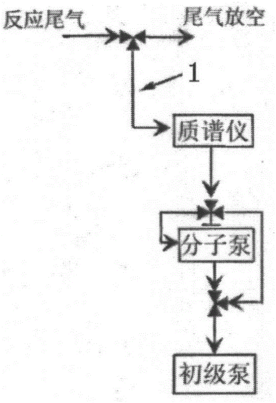
But this sampling method has some recognized disadvantages: 1) the working air pressure of the mass spectrometer changes with the sampling environment, for example, the background air pressure of the mass spectrometer remains at 10 when sampling at atmospheric pressure. -6 torr, the background pressure in the working area of ​​the mass spectrometer at 20 atmospheres may reach 10 -4 torr
At this time, the ionization region of the electric quadrupole of the mass spectrometer will have an ion chemical effect due to the greatly shortened molecular mean free path, and the sampling of the chemical reaction will directly affect the product signal
2) Capillary chromatography effect, that is, the real-time performance is not good, such as different aging delays for different gases, and timing broadening for pulse signals
3) The capillary is particularly thin and brittle, easy to break and difficult to replace

Method used


Image

  • Sampling apparatus of chromatographic effect eliminating type ultra-high vacuum chamber for high-pressure gas
  • Sampling apparatus of chromatographic effect eliminating type ultra-high vacuum chamber for high-pressure gas
  • Sampling apparatus of chromatographic effect eliminating type ultra-high vacuum chamber for high-pressure gas

Examples


Embodiment Construction

[0021] In order to make the present invention more comprehensible, preferred embodiments are described in detail below with accompanying drawings.

[0022] The present invention self-assembles the mass spectrometer in the laboratory implementation, and adopts imported PfeifferPrismaPlus electric quadrupole to match two PfeifferHiCube80KF interface molecular pump groups as a platform for testing the device of the present invention. The background air pressure is 5×10 when it is closed. -8 torr.

[0023] For related technical problems, the present invention has done the following considerations in design:

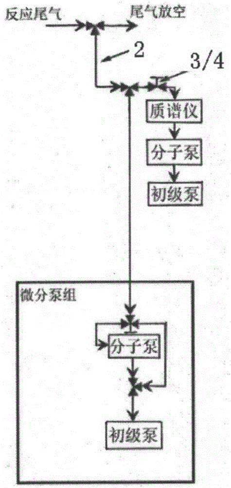
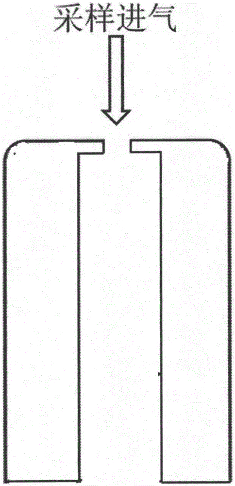
[0024] Firstly, the stainless steel capillary 2 is adopted, which is convenient for processing and refitting on the pipeline. At the same time, the airtightness of the sampling end in the high-pressure environment can be guaranteed through the common accessories of the pipeline, so as not to damage the working environment of the sampling end. Stainless steel capillary 2 use...


PUM


Abstract

The invention provides a sampling apparatus of a chromatographic effect eliminating type ultra-high vacuum chamber for the high-pressure gas. The apparatus is characterized by comprising an independently mounted stainless steel capillary used for sampling in a high-pressure environment, an independent differential pump set and a vacuum pump set directly connected with the ultra-high vacuum chamber. The differential pump set and the vacuum pump set are provided with completely blocked and independent pumping channels. The differential pump set and the vacuum pump set pump the gas out of the stainless steel capillary respectively through the pumping channels thereof. One part of the gas, pumped out of the stainless steel capillary, flows into the ultra-high vacuum chamber. The other part of the gas, pumped out of the stainless steel capillary, flows into the differential pump set. The ratio of the gas input into the ultra-high vacuum chamber to the gas input into the differential pump set can be adjusted by a needle valve or a high-precision flow valve. According to the technical scheme of the invention, the sampling requirements of ultra-high-pressure vacuum equipment in a large range of different pressure environments can be met at a relatively low cost. Meanwhile, a constant-pressure working environment is provided for vacuum protection type working test equipment.

Description

technical field [0001] The invention relates to a device for sampling from a high-pressure complex atmosphere environment to a mass spectrometer working area, and can also be used to provide other ultra-high vacuum equipment with gas sampling from a high-pressure area. Background technique [0002] Although the working principles of mass spectrometers are different, they all require a background pressure of 10 -8 Torr or lower vacuum environment protection, when working, the background pressure generally does not exceed 10 -5 torr, which is determined by the instrument working principle of the mass spectrometry acquisition device itself and the requirements for analysis accuracy. As for the sampling environment of mass spectrometry, except for a few in-situ analysis environments for basic scientific research that can directly meet the working environment requirements of the mass spectrometer itself, most of them meet the requirements of practical environmental analysis, suc...

Claims


Application Information

Patent Timeline
IPC IPC(8): H01J49/04
CPCH01J49/0404H01J49/0422
Inventor 杨永
Owner SHANGHAI TECH UNIV
Learn More