
Segmented holding claw vehicle clamp for engine end cover with small housing hole

An engine, segmented technology, applied in the field of tooling and fixtures, can solve the problems of low clamping efficiency, unstable size, warping, etc., to improve the processing quality, improve the clamping efficiency and the processing qualification rate, and achieve precise clamping. Effect

Active Publication Date: 2016-06-22
CHANGSHA BODA MACHINERY PARTS CO LTD
View PDF8 Cites 6 Cited by
  • Summary
  • Abstract
  • Description
  • Claims
  • Application Information

AI Technical Summary

Problems solved by technology

[0010] The object of the present invention is to solve the above problems and provide a segmented clamping jaw clamp for the engine end cover of a small casing hole, so as to solve the problem of low clamping efficiency of the clamp during turning processing, and unevenness of the workpiece due to improper clamping. Warping, which leads to the problem of unqualified product size; change the side clamping to the front part and the bottom matching segmental tension and compression method, to eliminate the problems of large ellipse, unstable size and product deformation during product processing; ensure the realization of workpiece Correct clamping improves clamping efficiency and processing pass rate

Method used


Image

  • Segmented holding claw vehicle clamp for engine end cover with small housing hole
  • Segmented holding claw vehicle clamp for engine end cover with small housing hole
  • Segmented holding claw vehicle clamp for engine end cover with small housing hole

Examples


Embodiment Construction

[0032] In order to enable those skilled in the art to better understand the technical solution of the present invention, the present invention will be described in detail below in conjunction with the accompanying drawings. The description in this part is only exemplary and explanatory, and should not have any limiting effect on the protection scope of the present invention. .

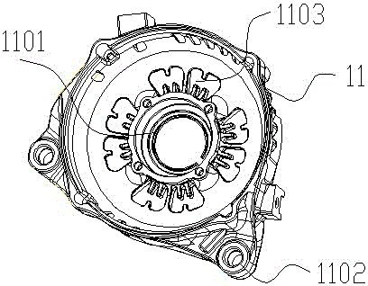
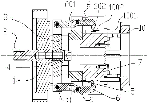
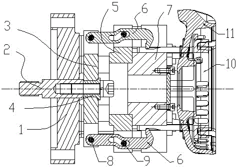
[0033] Such as Figure 2-Figure 8 As shown, the specific structure of the present invention is as follows: it includes a base 1, the base 1 is hollow, and a pull rod 2 is fitted therein, the front end of the pull rod 2 is connected with a four-headed lever 3; the front end of the four-headed lever 3 is provided with a transition Disk 5, the transition disk 5 is fixed on the base 1 and forms the activity space of the four-headed lever 3 together with the base 1; the four sides of the four-headed lever 3 are respectively connected with pull hooks 6 through hinge shafts 8, and the pull hooks 6 The waist-...


PUM


Abstract

The invention discloses a segmented holding claw vehicle clamp for an engine end cover with a small housing hole. The segmented holding claw vehicle clamp comprises a hollow base, wherein a pull rod is arranged inside the hollow base in a matching manner; the front end of the pull rod is connected to a four-head lever; a transition disc is arranged in front of the four-head lever and is fixed on the base; the transition disc and the base form the movement space of the four-head lever; the four sides of the four-head lever are connected to pull hooks respectively through articulated shafts; the pull hooks are movably fixed on the corresponding periphery of the transition disc through waist-shaped holes formed in the middle positions of the pull hooks; a positioning disc is arranged in front of the transition disc; pull hook grooves are formed in positions, corresponding to the pull hooks, of the positioning disc; and the positioning disc is provided with movable disassembling compressing plates matched with the pull hooks. The segmented holding claw vehicle clamp is used for solving the problems in a turning process that the clamp is low in clamping efficiency, and as the improper clamping results in unevenness and tilting of workpieces, the sizes of products are unqualified. The segmented holding claw vehicle clamp ensures realization of accurate clamping of the workpieces and improves clamping efficiency and machining percent of pass.

Description

technical field [0001] The invention belongs to the field of tooling fixtures, in particular to a segmented clamping claw clamp used for an engine end cover with a small casing hole. Background technique [0002] In the machining industry, turning is a commonly used machining method. Fixtures are used when the workpiece needs to be fixed during machining operations. The traditional clamping solution is to use a three-jaw clamp for clamping. In this clamping method, since the jaws of the three-jaw fixture have no directional reference, the operator must visually avoid the fixture from interfering with the clamped workpiece, and the clamping efficiency is low; and the directions of the clamped workpieces are different, which is likely to cause improper clamping As a result, the workpiece is unevenly loaded and warped, resulting in unstable processing and unqualified product dimensions. [0003] According to the above traditional three-jaw fixture clamping scheme, according ...

Claims


Application Information

Patent Timeline
IPC IPC(8): B23Q3/12
CPCB23Q3/12B23Q2703/10
Inventor 王庆端
Owner CHANGSHA BODA MACHINERY PARTS CO LTD
Learn More