
A device for measuring air flow in a pipeline

A technology of airflow flow and measuring device, which is applied in the field of flow rate and flow measurement of pulverized coal gas-solid two-phase fluid or single-phase high-temperature fluid flow rate and flow measurement, and can solve the problem that the actual flow rate and flow rate of the fluid cannot be truly reflected, and the measurement is difficult to take care of accurately The flow rate and coefficient of different temperature ranges are very different, so as to achieve the effect of improving safety and economy, reducing maintenance and reducing emissions

Active Publication Date: 2018-01-19
黄立新
View PDF9 Cites 0 Cited by
  • Summary
  • Abstract
  • Description
  • Claims
  • Application Information

AI Technical Summary

Problems solved by technology

However, due to the change of airflow temperature, the coefficient used to calculate the airflow velocity is very different, making it difficult to accurately take into account the flow velocity in different temperature ranges. Therefore, in the case of small temperature changes, the airflow velocity measured by the electrostatic charge method It can only reflect the change trend of the fluid velocity, but cannot truly reflect the actual flow velocity and flow rate of the fluid

Method used


Image

  • A device for measuring air flow in a pipeline

Examples


Embodiment Construction

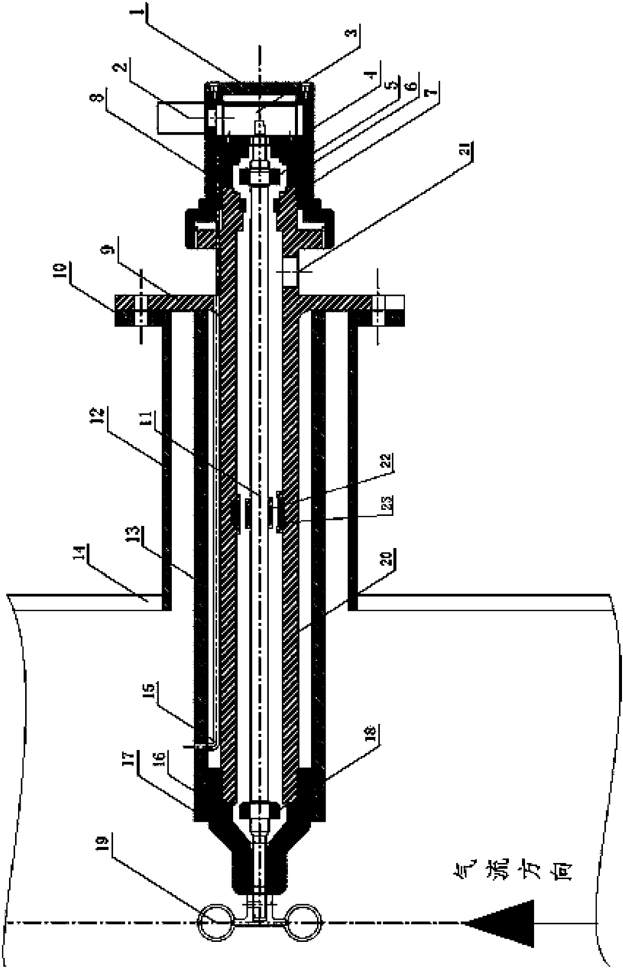
[0028] Below in conjunction with accompanying drawing and embodiment, the present invention is further described: as shown in Figure 1 pipeline air flow measuring device, comprises fan blade rotor 19, rotating shaft 11, measuring wind connecting pipe 20, rotational speed sensor 3, measuring wind pipe base 12 and data processor 2.

[0029] Among them, the speed sensor 3 is an encoder, which can convert the rotation angle into a pulse output. According to the accuracy of different types of encoders, it can output 360 to 2400 pulses per week. The data processor 2 can use PLC, single-chip or DSP to encode The output signal of the device can be directly connected to the data processor or DCS control system.

[0030] Fan blade rotor 19 is provided with three semicircular bowls or three fan blades that rotate around the shaft. The center line of the semicircular bowl or the fan blade is arranged on the central axis of the pipeline. The tail end of 11 is fixedly connected, and rotati...


PUM


Abstract

A flow measurement apparatus of pipe airflow is an apparatus for measuring a flow velocity or flow of a pipe gas-solid two-phase flow body or a single-phase high temperature flow body. A fan blade rotor arranged in the middle of a pipe is connected to a wind measurement connection pipe through a rotating shaft. The wind measurement connection pipe is connected to a pipe base flange welded on a pipe wall. The rotating shaft is connected to an upper pipe sleeve and a lower pipe sleeve installed on the wind measurement pipe base. Both ends of the rotating shaft are provided with magnets which fix positions of the rotating shaft and the wind measurement connection pipe through magnetic suspension force. The rotating shaft transmits output signals to a data processor through a rotating speed sensor for processing. The flow measurement apparatus of the pipe airflow uses the flow of a primary airpipe powder mixture to drive the fan blade rotor to rotate, and converts the rotating speed of the fan blade rotor into the wind speed of the pipe. The air output is calculated through a module processor. The piezometric pipe blocking problem in the measurement of the primary pneumatic pressure is avoided, and on-line monitoring of the wind speed or the wind quantity is realized. The apparatus service life is greatly prolonged by using a magnetic suspension technology, a sealing technology which uses high pressure cleaning air, and wear resistant materials.

Description

technical field [0001] The invention relates to the flow velocity and flow measurement of pulverized coal gas-solid two-phase fluid or the flow velocity and flow measurement technology of single-phase high-temperature fluid. Background technique [0002] In the combustion system of power plant boilers, the wind speed of the primary air duct is an important parameter for the combustion adjustment of the power plant boiler. If the primary wind speed is too high, it will easily cause unstable combustion of the boiler and even extinguish the fire; if the primary wind speed is too small, it will cause powder accumulation or blockage in the primary air duct , and even once the air duct was burned. For a long time, technicians have made too much effort to measure the velocity of the air-powder mixture in the primary air duct. Therefore, a variety of on-line monitoring technologies for the air-powder mixture in the primary air duct have been applied in the actual production of power...

Claims


Application Information

Patent Timeline
Patent Type & Authority Patents(China)
IPC IPC(8): G01D21/02
CPCG01D21/02
Inventor 黄立新
Owner 黄立新
Learn More