
A large wind turbine blade hinge mechanism

A technology for wind turbines and hinge mechanisms, which is applied to wind turbines, wind turbines consistent with the wind direction, and wind turbine control, etc., can solve the problems of weak power regulation capability, difficult design and manufacturing, and high manufacturing and maintenance costs, and achieves The effect of stable power, easy starting and large starting torque

Active Publication Date: 2018-11-09
HUANENG CLEAN ENERGY RES INST +1
View PDF5 Cites 0 Cited by
  • Summary
  • Abstract
  • Description
  • Claims
  • Application Information

AI Technical Summary

Problems solved by technology

The main structural features of fixed-pitch wind turbines are that the blades of the wind rotor and the hub are fixed and rigidly connected and cannot be moved. The principle of stall adjustment is adopted, which relies on the unique airfoil structure design of the blades. The airfoil structure is complex and difficult to design and manufacture. Weak power regulation
The blades of the variable-pitch wind turbine wind turbine are connected to the hub through bearings. When power adjustment is required, the blades rotate an angle relative to the hub, changing the pitch angle of the blades, thereby changing the ability of the blades to capture wind energy, thereby adjusting the wind force. The purpose of the output power of the generator set, this adjustment method has a large power adjustment range, but the hub structure of this wind turbine is complicated, the manufacturing and maintenance cost is high, and the reliability is poor

Method used


Image

  • A large wind turbine blade hinge mechanism
  • A large wind turbine blade hinge mechanism
  • A large wind turbine blade hinge mechanism

Examples


Embodiment Construction

[0020] The present invention will be described below in conjunction with the accompanying drawings and embodiments.

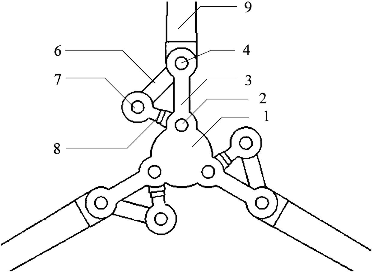
[0021] like figure 1 As shown, a large-scale wind turbine blade hinge mechanism includes a hub 1, and the hub 1 has three hub cantilevers 3 evenly distributed along the circumferential direction, and each hub cantilever 3 has a hinge hole at the top and root, and the hub cantilever 3 roots are rigid to the hub 1. Connected together, the top of the hub cantilever 3 is hinged through the second pin 4 and the top hinge hole of the support arm 6 of the paddle 9, and the bottom hinge hole of the support arm 6 is hinged with the top of the hydraulic cylinder 8 through the third pin 7. The bottom end of the cylinder 8 is hinged with the hinge hole at the root of the hub cantilever 3 through the first pin shaft 2, and the hydraulic cylinder 8, the hub cantilever 3 and the support arm 6 form a triangle connection.

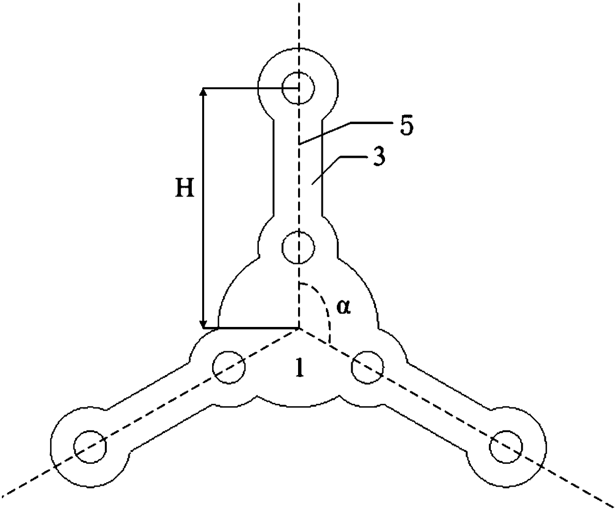
[0022] like figure 2 As shown, the blade 9 is compo...


PUM


Abstract

The invention discloses a hinging mechanism for blades of a large wind generating set. The hinging mechanism comprises a hub, wherein more than three hub cantilevers are uniformly arranged along the periphery of the hub; the root parts of the hub cantilevers are in rigid connection with the hub; the top end of each hub cantilever is hinged to a hinging hole at the top end of the support arm of a paddle blade through a second hinge pin; a hinging hole at the lower end of each support arm is hinged to the top end of a hydraulic cylinder through a third hinge pin; the bottom end of each hydraulic cylinder is hinged to a hinging hole at the root part of the corresponding hub cantilever through a first hinge pin; the hydraulic cylinders, the hub cantilevers and the support arms form rectangular connection; each paddle blade consists of the corresponding blade and the corresponding support arm which are rigidly connected; the blades can be rotated for a certain angle around hinge points at the top ends of the hub cantilevers through telescopic adjustment of the hydraulic cylinders; and through the rotation of the certain angle, the air-sweeping area of the wind wheel of a wind generator can be changed, and the pneumatic performance of the wind generator is changed, so that the stress of the wind generator and wind power captured by the wind generator are accordingly adjusted.

Description

technical field [0001] The invention relates to the technical field of wind power generation, in particular to a blade hinge mechanism of a large wind power generating set. Background technique [0002] Adopting large-scale wind turbines and large-scale transmission of wind power to the grid are the most important ways of wind power development. The magnitude of wind energy is greatly affected by the change of wind speed, and the change of wind speed has strong randomness, so wind energy is a very unstable energy source. However, if the electric energy generated by the wind turbines is to be transmitted to the grid, the wind turbines are required to have a relatively stable power output, and the output power is also subject to the constraints of the grid dispatch. The randomness of wind energy conflicts with the power stability required by the grid to accept wind power. In order to balance this contradiction, this puts forward high requirements on the power regulation capab...

Claims


Application Information

Patent Timeline
Patent Type & Authority Patents(China)
IPC IPC(8): F03D1/06F03D7/02
CPCF03D1/0658F03D7/0224Y02E10/72
Inventor 陈新明闫姝史绍平王保民许世森
Owner HUANENG CLEAN ENERGY RES INST
Learn More