A comprehensive landfill quasi-aerobic stabilization integrated system and its application
A technology for a landfill and an integrated system, which is applied in the field of quasi-aerobic stabilization integrated systems for a comprehensive landfill, can solve the problems of air pollution around the landfill, slow garbage stabilization rate, and low air diffusion efficiency, etc. Achieve the effect of preventing rainwater from entering the landfill layer, achieving rapid stabilization, and weakening the release strength
- Summary
- Abstract
- Description
- Claims
- Application Information
AI Technical Summary
Problems solved by technology
Method used
Image
Examples
Embodiment 1
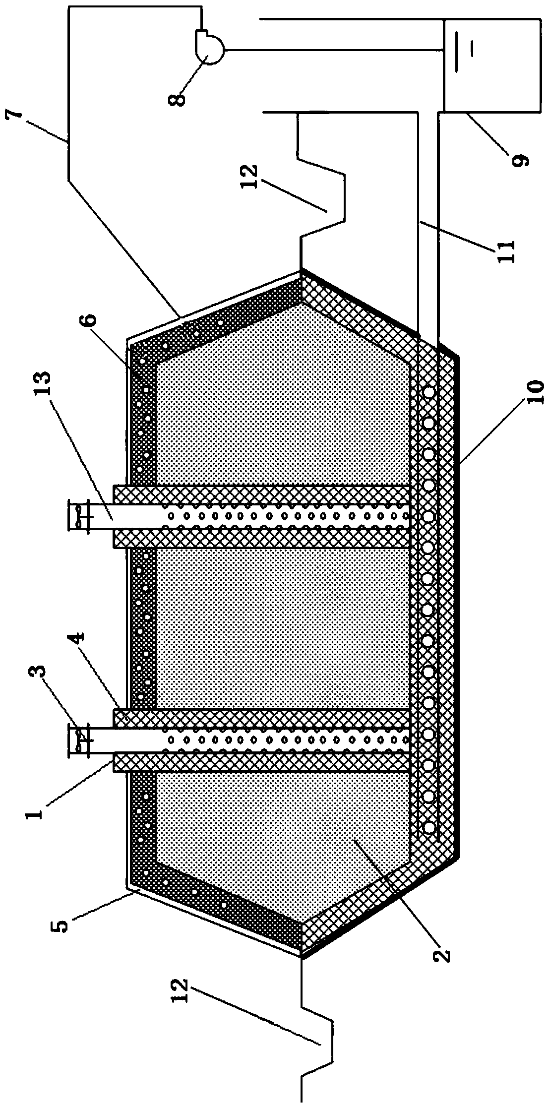
[0035] like figure 1 As shown, a comprehensive landfill quasi-aerobic stable integrated system, the system includes a landfill layer 2, a leachate collection and drainage layer arranged at the bottom of the landfill layer 2, and a leachate collection and drainage layer The connected leachate collection well 9, the quasi-aerobic landfill air-conducting unit arranged in the landfill layer 2, the leachate reinjection layer 6 arranged on the upper part of the landfill layer 2, and the leachate reinjection layer 6 and the seepage The filtrate collection well 9 is connected to the leachate circulation pipeline, and the landfill layer 2 is formed by mixing primary domestic waste and domestic waste incineration slag.
[0036] Among them, the leachate collection and drainage layer is composed of a porous leachate collection pipe 11 arranged at the bottom of the landfill layer 2. The porous leachate collection pipe 11 is connected to the leachate collection well 9, and the porous leacha...
Embodiment 2
[0047] In this embodiment, the inner diameter of the porous leachate collection pipe 11 is 650mm, the opening ratio of the upper half of the pipe wall is 15%, and the diameter of the seepage hole is 40mm.
[0048] The diameter of the vertical gas guide shaft 1 is 1.6m, the center is a perforated pipe 13, and the outer edge is a steel wire protection net; wherein, the inner diameter of the perforated pipe 13 is 175mm, and the pipe wall of the perforated pipe 13 is uniformly perforated except for each 1m at both ends. The hole diameter is 10mm. The malodorous gas purification packing layer 4 is formed by mixing domestic waste incineration slag, stable domestic waste and gravel in a mass ratio of 1:1:2.
[0049] The cross-sectional area of the leachate collection well 9 is 4m 2 , and the water level of the leachate in the leachate collection well 9 is lower than the leachate collection and drainage layer.
[0050] All the other are with embodiment 1.
Embodiment 3
[0052] In this embodiment, the inner diameter of the porous leachate collection pipe 11 is 500 mm, the opening ratio of the upper half of the pipe wall is 12%, and the diameter of the seepage hole is 20 mm.
[0053] The diameter of the vertical gas guide shaft 1 is 1.2m, the center is a perforated pipe 13, and the outer edge is a steel wire protection net; wherein, the inner diameter of the perforated pipe 13 is 150mm, and the pipe wall of the perforated pipe 13 is uniformly perforated except for each 1m at both ends. The hole diameter is 15mm. The malodorous gas purification packing layer 4 is formed by mixing domestic waste incineration slag, stable domestic waste and gravel in a mass ratio of 4:4:1.
[0054] The cross-sectional area of the leachate collection well 9 is 2.5m 2 , and the water level of the leachate in the leachate collection well 9 is lower than the leachate collection and drainage layer.
[0055] All the other are with embodiment 1.
PUM
| Property | Measurement | Unit |
|---|---|---|
| pore size | aaaaa | aaaaa |
| area | aaaaa | aaaaa |
| pore size | aaaaa | aaaaa |
Abstract
Description
Claims
Application Information
 - R&D
- Intellectual Property
- Life Sciences
- Materials
- Tech Scout
- Unparalleled Data Quality
- Higher Quality Content
- 60% Fewer Hallucinations
Browse by: Latest US Patents, China's latest patents, Technical Efficacy Thesaurus, Application Domain, Technology Topic, Popular Technical Reports.
© 2025 PatSnap. All rights reserved.Legal|Privacy policy|Modern Slavery Act Transparency Statement|Sitemap|About US| Contact US: help@patsnap.com

