
Automatic emergency braking system for automobiles and control method of automatic emergency braking system

An automatic braking and automobile technology, applied in the direction of automatic starting devices, brakes, vehicle components, etc., can solve the problems of no automatic braking device, no detailed automatic braking device and control method, etc., to prevent passenger injuries, improve reliability and stability. performance and energy consumption reduction

Active Publication Date: 2016-06-15
TRW AUTOMOTIVE COMPONENTS SHANGHAI
View PDF9 Cites 6 Cited by
  • Summary
  • Abstract
  • Description
  • Claims
  • Application Information

AI Technical Summary

Problems solved by technology

[0003] The application number is 201210100625.6, a radar ranging automatic braking system. This invention discusses the principle of the automatic braking system. It controls the alarm module to perform alarm and braking of the braking module according to the distance between the car and the obstacle. However, this invention does not Detailed automatic braking device and control method; the application number is 201510249348.9, a vehicle automatic braking device and its method, the invention calculates the collision time between the vehicle and the obstacle, and controls the braking module to perform full braking or partial braking on the vehicle. Invention also has no corresponding automatic braking device

Method used


Image

  • Automatic emergency braking system for automobiles and control method of automatic emergency braking system
  • Automatic emergency braking system for automobiles and control method of automatic emergency braking system
  • Automatic emergency braking system for automobiles and control method of automatic emergency braking system

Examples


Embodiment Construction

[0034] The present invention will be described in further detail below in conjunction with the specific embodiments of the accompanying drawings, but the protection scope of the present invention is not limited thereto.

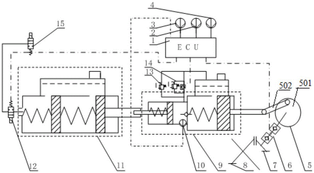
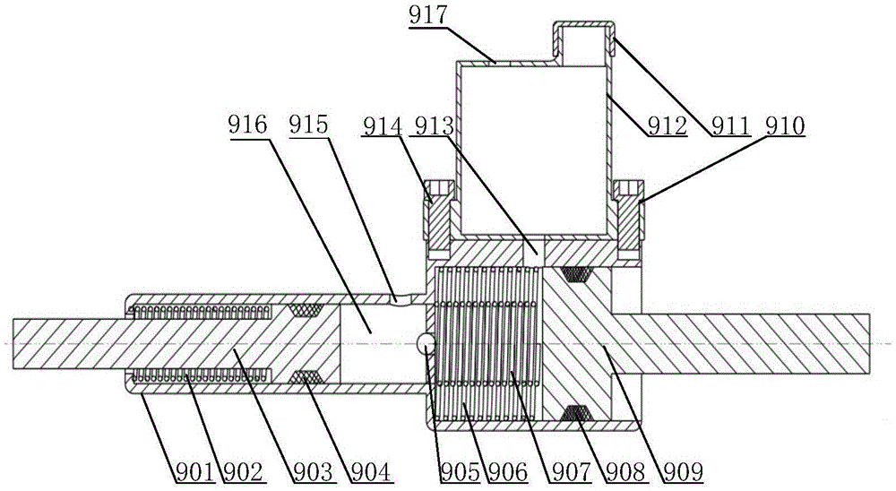
[0035] like figure 1 Shown is an embodiment of the automobile emergency automatic braking system of the present invention. In this embodiment, the automobile emergency automatic braking system includes a detection mechanism, an actuator, a hydraulic booster 9, and an additional brake master cylinder 11 and electronic control unit 1.

[0036] The detection mechanism includes a vehicle speed sensor 2, a radar ranging sensor 3, a brake pedal stroke sensor 4 and a hydraulic pressure sensor 10; the vehicle speed sensor 2 is used to detect the speed of the car, and the radar ranging sensor 3 is used to detect obstacles The distance between the object and the car, the brake pedal stroke sensor 4 is used to detect whether the driver steps on the brake pedal to brake...


PUM


Abstract

The invention relates to an automatic emergency braking system for automobiles and a control method of the automatic emergency braking system, belonging to the field of safe driving of vehicles. The automatic emergency braking system comprises a detection mechanism, an execution mechanism, a hydraulic pressurizing device, an auxiliary braking main cylinder and an electronic control unit; the hydraulic pressurizing device is driven by a driving force of a driving shaft of an automobile to control the pressure of hydraulic oil in a high-pressure cavity of the hydraulic pressurizing device to control a piston a to move, and the piston a pushes the auxiliary braking main cylinder so as to realize grading braking; and the electronic control unit calculates whether the automobile is located at a first safe position S1, a second safe position S2, a second dangerous position S3 or a first dangerous position S4 in real time according to the speed of the automobile or the distance from the automobile to a barrier and controls the execution mechanism to work according to the distance of the automobile, so as to stably and efficiently realize the automatic braking of the automobile. According to the automatic emergency braking system, the hydraulic pressurizing device is driven by virtue of the driving shaft of the automobile, so that the power consumption of an additional electric motor is avoided during the braking, and therefore, the energy consumption is reduced; and by virtue of the grading braking, the riding comfort level is improved.

Description

technical field [0001] The invention belongs to the field of driving safety, and in particular relates to an automobile emergency automatic braking system and a control method thereof. Background technique [0002] With the increase in the number of cars, traffic accidents are also gradually increasing, and car safety has become an important issue of concern to the industry. Many safety technologies have emerged as the times require, and automatic braking technology has gradually matured and been applied; As the latest active safety technology, it can help drivers avoid rear-end collisions in urban traffic at low speeds; Mercedes-Benz is one of the earliest car companies to conduct safety research, so it also has high achievements in pre-collision safety systems. At present, the well-known pre-safe pre-collision safety system has been popularized to C-class, E-class and S-class; Toyota's pre-collision safety system is called Pre-Collision System, PCS for short. With its adva...

Claims


Application Information

Patent Timeline
IPC IPC(8): B60T7/12B60T13/70
CPCB60T7/12B60T13/70
Inventor 徐兴卢山峰陈龙孙晓东陈特
Owner TRW AUTOMOTIVE COMPONENTS SHANGHAI
Learn More