
Tool parameter measurement device based on CCD and measurement method of device

A technology for parameter measurement and tooling, which is used in measurement/indication equipment, manufacturing tools, metal processing equipment, etc., and can solve problems such as reduced efficiency and accuracy impact.

Active Publication Date: 2016-06-15
SHANDONG UNIV
View PDF8 Cites 9 Cited by
  • Summary
  • Abstract
  • Description
  • Claims
  • Application Information

AI Technical Summary

Problems solved by technology

In order to ensure the safe and reliable operation of the spindle system, the spindle-tool holder-tool joint surface needs to have the characteristics of high geometric accuracy, high repeatability and high rigidity, and the joint surface has an important influence on the dynamic characteristics of the high-speed spindle system; and Considering the actual production conditions of the factory, the tool is stored in the tool magazine, and the spindle-tool-tool holder joint surface has been positioned. According to the proposed measurement plan, the tool needs to be unloaded from the tool magazine first, and then unloaded from the tool holder. One installation requires two repositionings, which reduces the efficiency and has a direct impact on the accuracy of the obtained tool parameters

Method used


Image

  • Tool parameter measurement device based on CCD and measurement method of device
  • Tool parameter measurement device based on CCD and measurement method of device
  • Tool parameter measurement device based on CCD and measurement method of device

Examples


Embodiment Construction

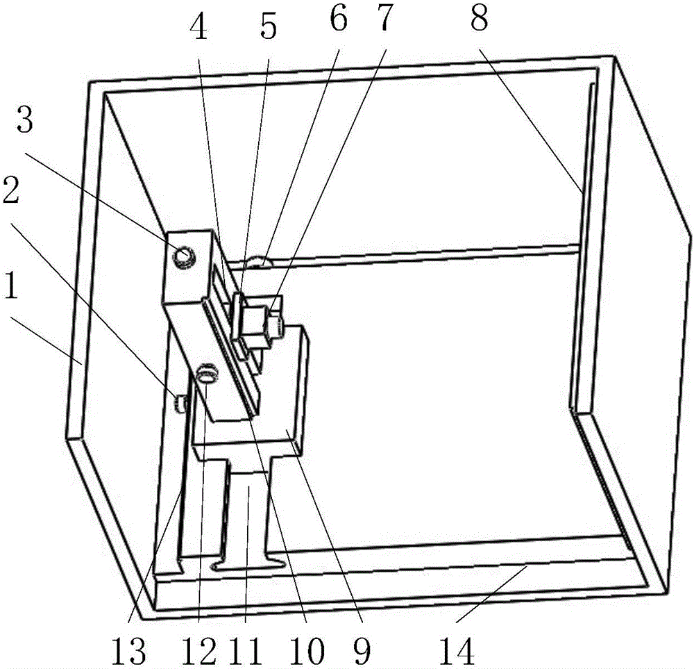
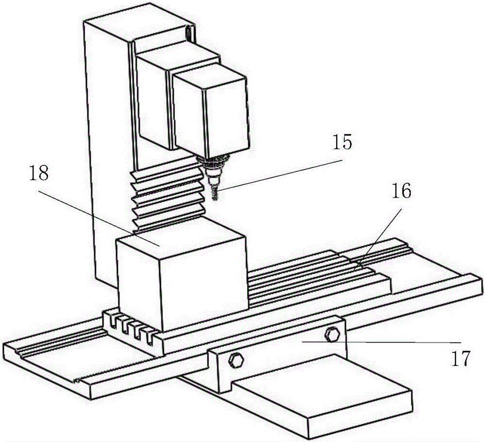
[0049] like figure 1Shown, the tool parameter measuring device based on CCD of the present invention comprises acquisition box 18, CCD industrial camera 7, industrial computer (not shown in the figure) and display (not shown in the figure), CCD industrial camera 7, industrial computer and display Connect sequentially. Collection box 18 is to be provided with casing 1 on its base 14 and forms, and casing 1 comprises four side box doors and a top box door ( figure 1 The top box door and one side box door are omitted in the middle), and each box door is movable and can be opened. The base 14 of the collection box 18 is provided with a camera lateral movement mechanism, the camera lateral movement mechanism is provided with a camera longitudinal movement mechanism, and the CCD industrial camera 7 is installed on the camera longitudinal movement mechanism. The LED light source board 8 is also arranged in the collection box 18, and the LED light source board 8 is used for lighting...


PUM


Abstract

The invention relates to a tool parameter measurement device based on a CCD and a measurement method of the device.The tool parameter measurement device comprises a collection box, a CCD industrial camera, an industrial personal computer and a display, and the CCD industrial camera, the industrial personal computer and the display are sequentially connected; a camera transverse moving mechanism is arranged on a base of the collection box, a camera longitudinal moving mechanism is arranged on the camera transverse moving mechanism, and the CCD industrial camera is installed on the camera longitudinal moving mechanism.When measurement is conducted, a machine tool main shaft does not rotate, and static collecting is conducted; the main shaft collects an image whenever the main shaft rotates by one angle, and peripheral morphology of a tool is collected and stored in the specific location; data processing is conducted on a collected gray image.According to the tool parameter measurement device based on the CCD and the measurement method of the device, the tool parameters are directly measured on a machine tool, tool disassembly is omitted, the precision and efficiency are improved, non-contact measurement is conducted on a digital image based on the CCD, static measurement is conducted on the tool parameters, and the cost is reduced compared with that of a camera needing automatic focusing under rotation; the parameters such as slack length, radius, fillet and form and location tolerance of the tool can be measured.

Description

technical field [0001] The invention relates to a measuring device and a measuring method for directly and accurately obtaining geometric parameters such as overhang length, radius, fillet, shape tolerance and the like of a tool on a machine tool, and belongs to the technical field of tool geometric parameter measurement. Background technique [0002] As a professional tool for CNC machine tools to process precision parts, the cutting tool's own precision directly determines the precision of the precision parts it processes. The current tool measurement method has certain limitations. First, manual measurement of tool parameters is not suitable for the current batch production and high automation of CNC machining centers. Manual detection has low efficiency and low precision; the surface of the tool and the processed features require high precision and high surface finish. The traditional method needs to contact the measuring tool with the surface of the tool, which will dam...

Claims


Application Information

Patent Timeline
IPC IPC(8): B23Q17/00B23Q17/24
CPCB23Q17/00B23Q17/2457B23Q17/249
Inventor 孙杰侯秋林李楠姜振喜国凯
Owner SHANDONG UNIV
Learn More