Special equipment for machining head of air intake welding manifold of automobile

A special equipment and manifold technology, which is applied in the field of special equipment for processing the head of the automobile intake welding manifold, can solve the problems of affecting the production and processing efficiency, affecting the processing accuracy, and violent vibration, so as to facilitate cleaning and processing and improve work safety degree, the effect of increasing the cutting speed

Active Publication Date: 2016-06-15
JIANGYIN CHUANGBO MACHINERY MFG CO LTD
View PDF7 Cites 2 Cited by
  • Summary
  • Abstract
  • Description
  • Claims
  • Application Information

AI Technical Summary

Problems solved by technology

[0002] For automobile engines, the outlet manifold is the outlet pipe before the outlet port of the cylinder head. It is used for exhaust after high-temperature combustion of the engine and to mix the outlet port. It is mainly high temperature, so it requires good welding performance. When high temperature and high frequency vibration are generated , the welding cannot be cracked, and at the same time, it is required to be able to seamlessly connect with the machined flange after welding to ensure the gas outlet. The existing processing method takes a long time to process the head of the intake manifold, which affects the production and processing efficiency, and the existing Processing method, during the rotation of the workpiece, due to the irregular shape of the head of the automobile manifold, severe vibration will occur during rotation, which will affect the processing accuracy, so the workpiece rotates slowly, causing great wear on the tool and slow processing speed. Moreover, the existing processing method , every time the workpiece is processed, the motor needs to be restarted, which wastes a lot of time

Method used


Image

  • Special equipment for machining head of air intake welding manifold of automobile
  • Special equipment for machining head of air intake welding manifold of automobile
  • Special equipment for machining head of air intake welding manifold of automobile

Examples


Embodiment Construction

[0038] The present invention will be described in further detail below in conjunction with the accompanying drawings.

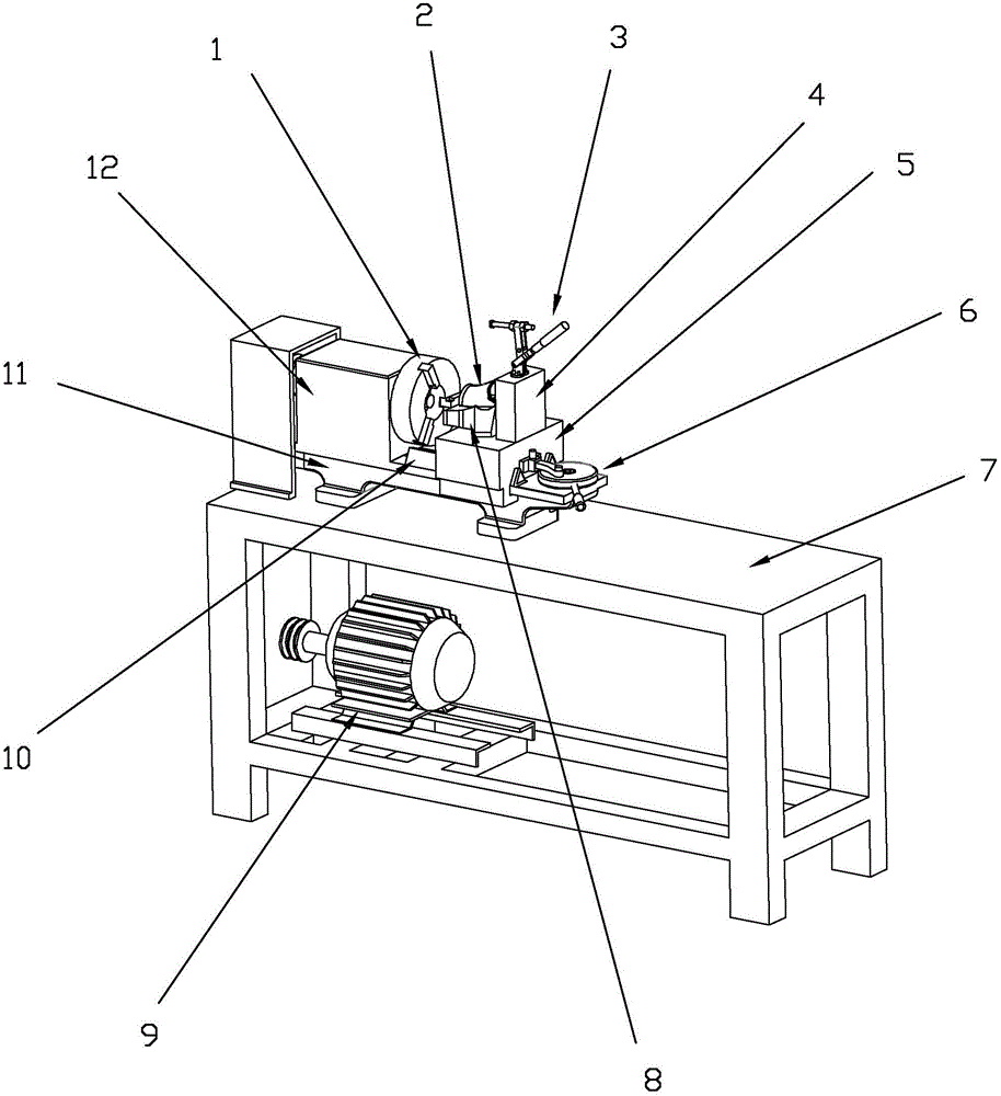
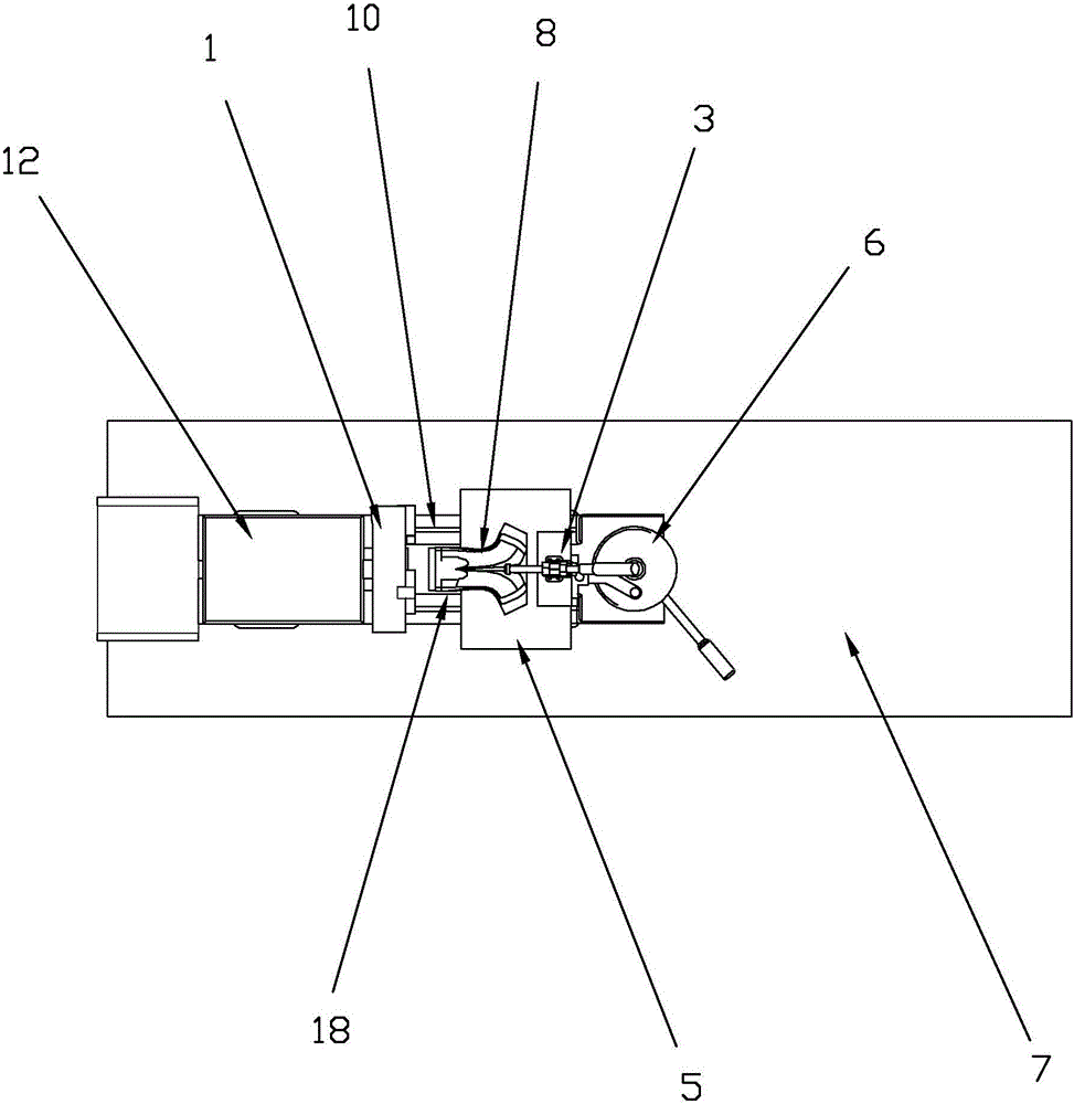
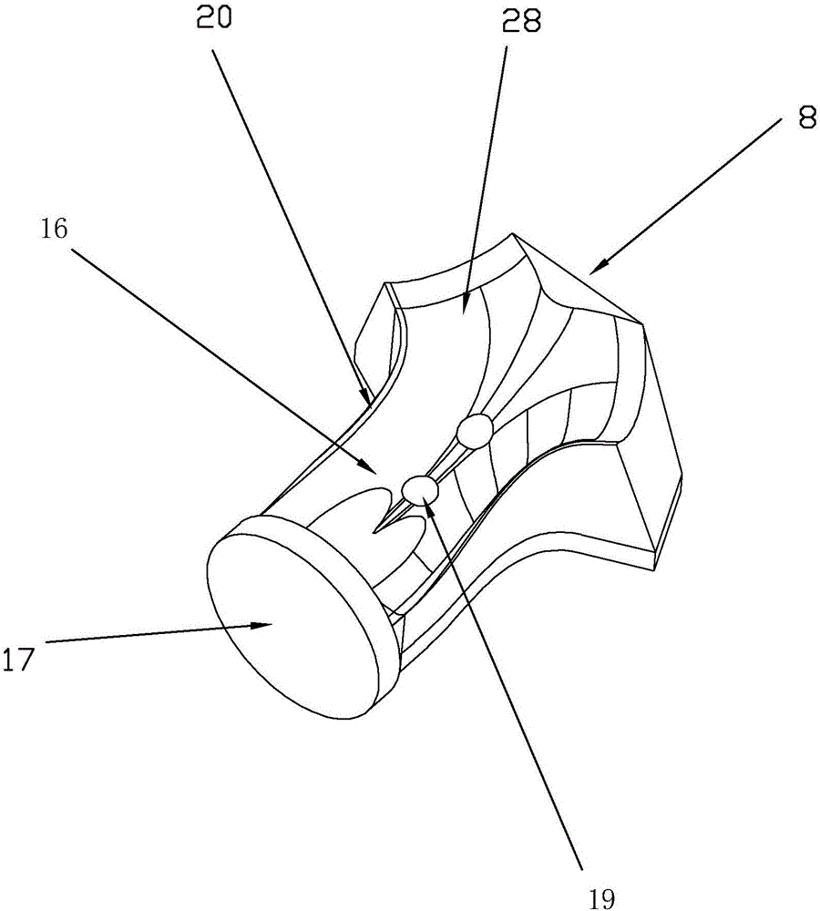
[0039] Such as figure 1 As shown, a special equipment for processing the head of an automobile intake welding manifold includes a frame body 7, a bed 11 is provided on the frame body 7, a slide rail 10 is provided on the bed 11, and a cutter head located at one end of the slide rail 10 1 and the driving device 6 positioned at the other end of the slide rail 10, the slide rail 10 is slidably connected with a workpiece holder 5, the workpiece holder 5 is provided with a fixed block 8 for fixing the manifold 2 to be processed, and is also provided with a workpiece The fixed block 8 cooperates and fastens the fixture 3 of the manifold 2 to be processed, and the surface of the cutter head 1 facing the workpiece holder 5 is provided with an inner cavity 14 for the manifold head to extend into, and the opening edge of the inner cavity 14 is evenly distributed for T...


PUM


Abstract

The invention discloses special equipment for machining a head of an air intake welding manifold of an automobile, and belongs to the field of automobile accessory machining. The special equipment comprises a machine body, wherein a cutter head, a workpiece fixing seat for fixing the head of the manifold and a sliding rail are arranged on the machine body; the workpiece fixing seat is connected to the sliding rail in a sliding manner and faces the cutter head; an inner cavity for letting the head of the manifold extend is formed in the cutter head; cutters for machining the head of the manifold are uniformly arrayed at the edge of an opening, which faces the workpiece fixing seat, of the inner cavity; and the cutter head is arranged at one end of the sliding rail, and a driving device for driving the workpiece fixing seat to move along the sliding rail is arranged at the other end of the sliding rail. The special equipment is high in manifold head machining speed and high in production processing efficiency.

Description

technical field [0001] The invention relates to the field of auto parts processing, in particular to a special equipment for processing the head of an auto intake welding manifold. Background technique [0002] For automobile engines, the outlet manifold is the outlet pipe before the outlet port of the cylinder head. It is used for exhaust after high-temperature combustion of the engine and to mix the outlet port. It is mainly high temperature, so it requires good welding performance. When high temperature and high frequency vibration are generated , the welding cannot be cracked, and at the same time, it is required to be able to seamlessly connect with the machined flange after welding to ensure the gas outlet. The existing processing method takes a long time to process the head of the intake manifold, which affects the production and processing efficiency, and the existing Processing method, during the rotation of the workpiece, due to the irregular shape of the head of t...

Claims


Application Information

Patent Timeline
Patent Type & Authority Applications(China)
IPC IPC(8): B23B5/08B23Q3/06
CPCB23B5/08B23Q3/065
Inventor 顾佳铭蒋盛
Owner JIANGYIN CHUANGBO MACHINERY MFG CO LTD
Why Eureka
Try Eureka