
Power supply system and power supply method in sdi mode

A technology of power supply system and mode, applied in CCTV systems, components of TV systems, TVs, etc., can solve the problems of large investment, real-time video transmission requirements affecting image definition, slow implementation of high-definition video detection, etc. strong effect

Active Publication Date: 2017-12-22
FUJIAN FORECAM OPTICS CO LTD
View PDF5 Cites 0 Cited by
  • Summary
  • Abstract
  • Description
  • Claims
  • Application Information

AI Technical Summary

Problems solved by technology

[0002] At present, in the occasions where real-time detection requirements are high, the method of analog video is still used to obtain video images, but such detection methods can no longer meet the requirements of high-definition and high-comprehension visual detection. In order to be able to perform high-definition video Transmission, now commonly used means is parallel data transmission, such as CAMERA Link, DVI or HDMI, these transmission methods need to re-improved the existing project, or the whole project needs to be redesigned, from the engineering cost or system transformation aspects of investment Large enough to be slow to advance implementation of HD video detection
[0003] Now for the detection of non-real-time occasions, network communication is mainly used. In order to reduce the power supply problem of wiring, voltage signals are transmitted at the same time during network communication. Although this design can transmit images, network transmission needs to compress the video or need to follow the network protocol. Transmission, which affects the clarity of the image and the real-time transmission requirements of the video

Method used


Image

  • Power supply system and power supply method in sdi mode
  • Power supply system and power supply method in sdi mode
  • Power supply system and power supply method in sdi mode

Examples


Embodiment Construction

[0031] The technical solution of the present invention will be specifically described below in conjunction with the accompanying drawings.

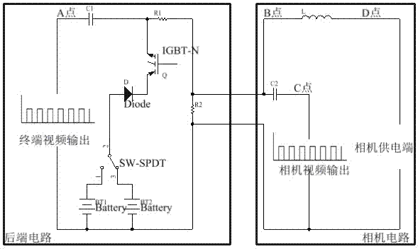
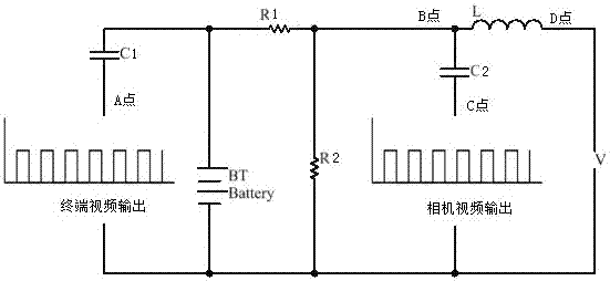
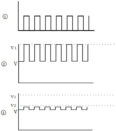
[0032] A power supply system in SDI mode of the present invention includes a control module and an SDI power supply module connected to the control module. The SDI power supply module detects the voltage and current signals input by the connected video input device through the SDI coaxial cable, and transmits the to the control module, and then the control module controls the working mode of the SDI power supply module according to the voltage and current signals detected by the detection module. The SDI power supply module includes a power supply switch IGBT, a power supply switching switch SW-SPDT, a first power supply BT1, a second power supply BT2 and a first resistor R1, and one end of the power supply switch is connected to the first power supply, The second power supply is connected, the other end of the power supply switch is conn...


PUM


Abstract

The invention relates to a power supply system and a power supply method in SDI mode. The system includes a control module and an SDI power supply module connected to the control module. The SDI power supply module detects the voltage and current signals input by the connected video input device and transmits them to the control module, and then the control module detects the voltage and current according to the detection module. The signal controls the working mode of the SDI power supply module; the SDI power supply module includes a power supply switch, a power switch, a first power supply, a second power supply and a first resistor, and one end of the power supply switch is respectively connected to the first power supply and the second power supply through the power supply switch , the other end of the power supply switch is connected to the first resistor, and the SDI power supply module realizes detection of voltage and current signals input by the video input device through the first resistor. The invention can reduce the wiring of the video monitoring, can realize the power supply of the camera and the signal transmission of the video by using a coaxial cable, improves the reliability of the system work and simplifies the layout and wiring of the system.

Description

technical field [0001] The invention relates to a power supply system and a power supply method in SDI mode. Background technique [0002] At present, in the occasions where real-time detection requirements are high, the method of analog video is still used to obtain video images, but such detection methods can no longer meet the requirements of high-definition and high-comprehension visual detection. In order to be able to perform high-definition video Transmission, now commonly used means is parallel data transmission, such as CAMERA Link, DVI or HDMI, these transmission methods need to re-improved the existing project, or the whole project needs to be redesigned, from the engineering cost or system transformation aspects of investment Large enough to be slow to advance the implementation of high-definition video detection. [0003] Now for the detection of non-real-time occasions, network communication is mainly used. In order to reduce the power supply problem of wiring...

Claims


Application Information

Patent Timeline
Patent Type & Authority Patents(China)
IPC IPC(8): H04N5/225H04N7/10H04N7/18
CPCH04N7/10H04N7/18H04N23/50
Inventor 车国锋王颖军何文波
Owner FUJIAN FORECAM OPTICS CO LTD
Learn More