Method and device for continuously adjusting data transmission clock

A data transmission and adjustment method technology, applied in the field of data transmission, can solve the problems of poor data reception reliability and low data transmission rate, and achieve the effects of improving stability, reducing jitter, and increasing speed

Active Publication Date: 2019-03-08
SPACE STAR TECH CO LTD
View PDF5 Cites 0 Cited by
  • Summary
  • Abstract
  • Description
  • Claims
  • Application Information

AI Technical Summary

Problems solved by technology

However, using this method to adjust the clock frequency, because the change of the clock frequency is hopping, it will cause the problems of poor reliability of data reception and low data transmission rate.

Method used


Image

  • Method and device for continuously adjusting data transmission clock
  • Method and device for continuously adjusting data transmission clock
  • Method and device for continuously adjusting data transmission clock

Examples


Embodiment 1

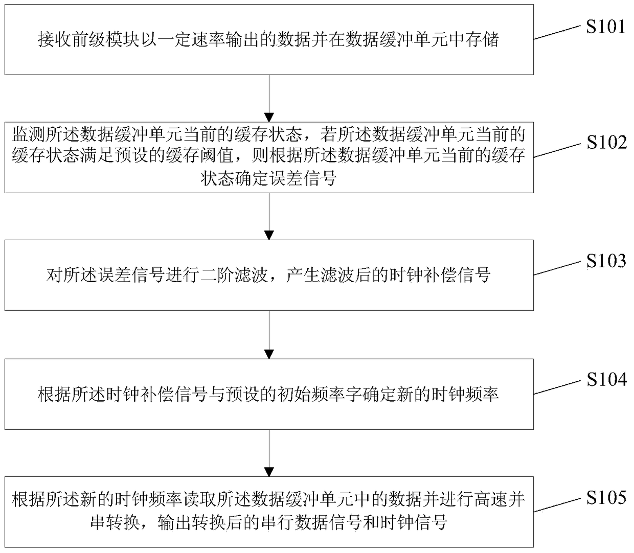
[0027] figure 1 It is a schematic flow chart of the method for continuously adjusting the data transmission clock described in Embodiment 1 of the present invention, as shown in figure 1 As shown, the method may include the following steps:

[0028] Step S101, receiving the data output by the front-end module at a certain rate and storing it in the data buffer unit;

[0029] Step S102, monitoring the current buffering state of the data buffering unit, and determining an error signal according to the current buffering state of the data buffering unit if the current buffering state of the data buffering unit satisfies a preset buffering threshold;

[0030] Step S103, performing second-order filtering on the error signal to generate a filtered clock compensation signal;

[0031] Step S104, determining a new clock frequency according to the clock compensation signal and the preset initial frequency word;

[0032] Step S105, read the data in the data buffer unit according to the...

Embodiment 2

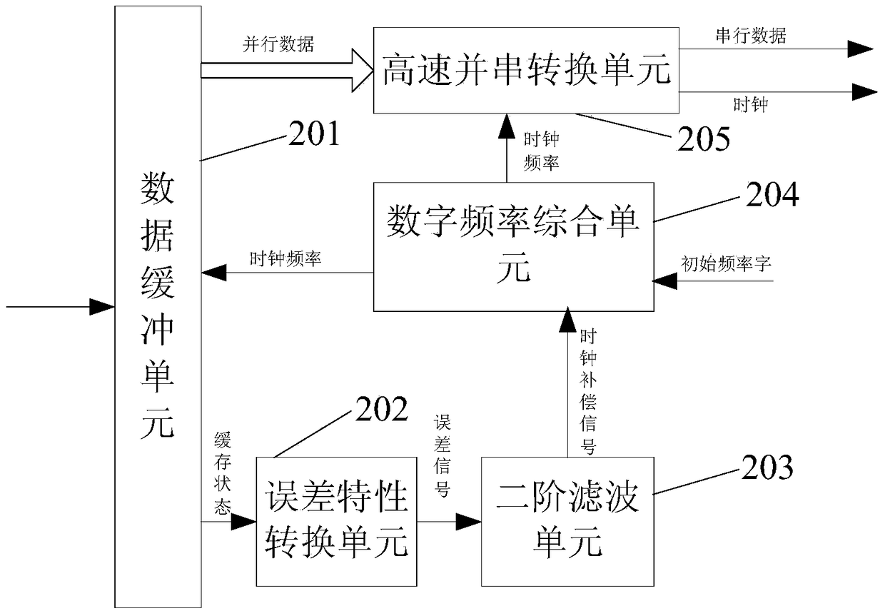
[0041] figure 2 It is a structural block diagram of the data transmission clock continuous adjustment device described in the second embodiment of the present invention, as shown in figure 2 As shown, the data transmission clock continuous adjustment device described in this embodiment may include:

[0042] The data buffer unit 201 is used to receive and store the data output by the previous module at a certain rate;

[0043] An error characteristic conversion unit 202, configured to monitor the current buffer state of the data buffer unit, and determine an error signal according to the current buffer state of the data buffer unit if the current buffer state of the data buffer unit satisfies a preset buffer threshold ;

[0044] A second-order filtering unit 203, configured to perform second-order filtering on the error signal to generate a filtered clock compensation signal;

[0045] A digital frequency synthesis unit 204, configured to determine a new clock frequency acc...


PUM


Abstract

The embodiment of the invention discloses a method and a device for continuously adjusting a data transmission clock. The method comprises the steps of receiving data transmitted by a front end module and storing in a data buffer unit; determining an error signal through monitoring the current cache state of the data buffer unit; performing second order filtering and other processing on the error signal and thereby determining a new clock frequency; and reading the data in the data buffer unit according to the new clock frequency and performing high-speed serial parallel conversion, and outputting a serial data signal and a clock signal after conversion. Therefore, the data clock frequency is continuously adjusted, and finally converged to the actual data transmission speed, thus the stability of the clock frequency in high-speed transmission is improved and the jitter of the clock frequency in high-speed transmission is reduced, and furthermore the data receiving reliability of the receiving end can be increased, and the data transmitting and receiving speed can be improved.

Description

technical field [0001] The invention relates to the field of data transmission, in particular to digital information transmission technology, in particular to a method and device for continuously adjusting a data transmission clock. Background technique [0002] In a communication or data processing system, high-speed data interaction is often required between devices. For some special devices, due to the lack of interfaces based on complex protocols such as network ports, the data interaction between devices usually uses a relatively simple level interface. For example, a series of level interface standards formed in the prior art to meet such applications: RS232, LVDS (Low Voltage Differential Signaling, that is, low voltage differential signal technology interface), ECL (Emitter Coupled Logic, that is, emitter Coupled logic circuit) and other interface standards. [0003] Among them, the RS232 interface standard adopts asynchronous transmission mode, and there is no data...

Claims


Application Information

Patent Timeline
Patent Type & Authority Patents(China)
IPC IPC(8): H04L1/00
Inventor 陈昕李璇陈茹梅宋振宇李博
Owner SPACE STAR TECH CO LTD
Why Eureka
Try Eureka