
Optimization method of flexible push-pull cable-based angular displacement signal feedback system

A technology of signal feedback and optimization methods, applied in general control systems, control/regulation systems, instruments, etc., can solve the uncertainty of data point measurement results, difficulties in debugging and installation by on-site workers, and difficulty in accurately grasping the motion laws of feedback systems and other problems to achieve the effect of solving irregular curves, reducing working time and improving accuracy

Inactive Publication Date: 2016-06-08
AECC SHENYANG ENGINE RES INST
View PDF5 Cites 0 Cited by
  • Summary
  • Abstract
  • Description
  • Claims
  • Application Information

AI Technical Summary

Problems solved by technology

Due to the limited number of data points obtained through experiments and the uncertainty of measurement results, it is difficult for designers to accurately grasp the motion law of the feedback system
At the same time, because there is no design and optimization method for the displacement signal feedback system based on the flexible shaft push-pull cable, it has caused difficulties in the design of the flexible shaft push-pull feedback system and the debugging and installation of on-site workers.

Method used


Image

  • Optimization method of flexible push-pull cable-based angular displacement signal feedback system
  • Optimization method of flexible push-pull cable-based angular displacement signal feedback system
  • Optimization method of flexible push-pull cable-based angular displacement signal feedback system

Examples


Embodiment Construction

[0020] In order to make the objectives, technical solutions and advantages of the present invention clearer, the technical solutions in the embodiments of the present invention will be described in more detail below in conjunction with the drawings in the embodiments of the present invention. In the drawings, the same or similar reference numerals denote the same or similar elements or elements having the same or similar functions throughout. The described embodiments are some, but not all, embodiments of the invention. The embodiments described below by referring to the figures are exemplary and are intended to explain the present invention and should not be construed as limiting the present invention. Based on the embodiments of the present invention, all other embodiments obtained by persons of ordinary skill in the art without creative efforts fall within the protection scope of the present invention. Embodiments of the present invention will be described in detail below ...


PUM


Abstract

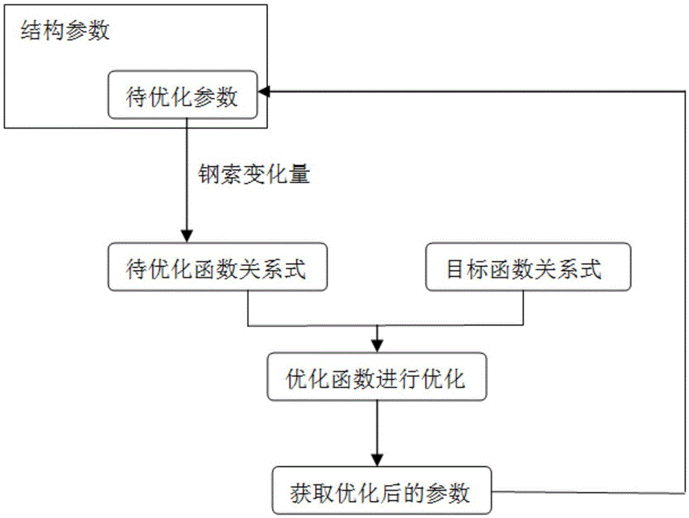
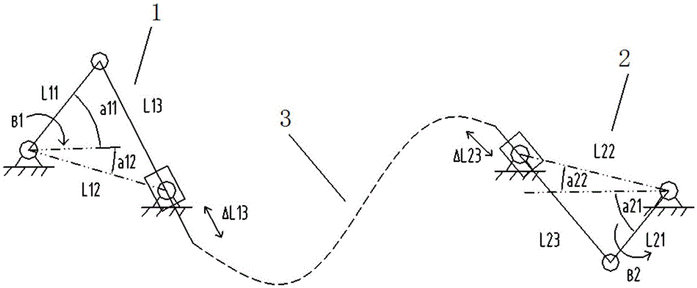
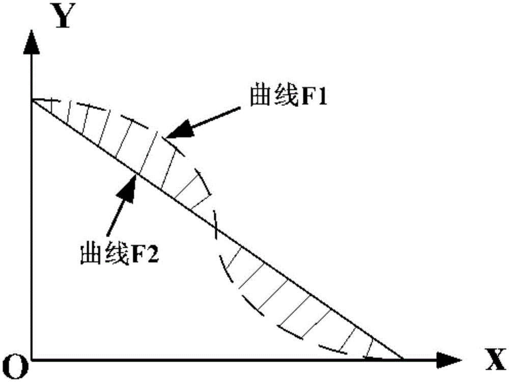
The invention discloses an optimization method of a flexible push-pull cable-based angular displacement signal feedback system. The method includes the following steps that: step 1, a flexible push-pull cable-based angular displacement signal feedback system geometric model is constructed, the structural parameters of a driving angular displacement mechanism and a driven angular displacement mechanism are acquired; step 2, a function relational expression to be optimized is constructed according to the bevel edge length variation quantity of the driving angular displacement mechanism and the driven angular displacement mechanism, wherein the function relational expression to be optimized contains two parameters to be optimized, namely a driving component structural parameter m and a driven component structural parameter n, which are obtained in step 1; step 3, a target function relational expression of angle variation in the swing of rocker arms of the driving angular displacement mechanism and the driven angular displacement mechanism is provided; and step 4, a curve corresponding to the function relational expression to be optimized and a curve corresponding to the target function relational expression are fitted to each other through an optimization function, and the parameter m to be optimized and the parameter n to be optimized are calculated. With the method of the invention adopted, the acquisition of movement laws in the flexible push-pull cable-based angular displacement signal feedback system can be improved.

Description

technical field [0001] The invention belongs to the design field of an aeroengine displacement signal feedback system, and in particular relates to an optimization method of an angular displacement signal feedback system based on a flexible shaft push-pull steel cable. Background technique [0002] The displacement signal feedback system based on the flexible shaft push-pull cable is widely used in the aero-engine control system. The "angular displacement-linear displacement-angular displacement" displacement signal feedback system composed of flexible shaft push-pull feedback steel cables realizes the transmission of motion relations, such as aeroengine α 1 、α 2 The control laws are all realized based on the above systems. [0003] At present, the kinematic relationship of the displacement signal feedback system based on the flexible shaft push-pull cable is obtained through experimental tracing. Due to the limited number of data points obtained through experiments and t...

Claims


Application Information

Patent Timeline
IPC IPC(8): G05B13/04
CPCG05B13/042
Inventor 刘永泉郑伟连金海周伟朋李润泽
Owner AECC SHENYANG ENGINE RES INST
Learn More