
Testing apparatus of conductivity and electrical equipment

A test device and conductivity technology, applied in the direction of measurement device, measurement of resistance/reactance/impedance, measurement of electrical variables, etc., can solve the problems of inaccurate test results, cumbersome user operations, and inability to provide users, and enhance test diversity. , to ensure accuracy and avoid the effect of interference

Active Publication Date: 2016-06-08
FOSHAN SHUNDE MIDEA ELECTRICAL HEATING APPLIANCES MFG CO LTD +1
View PDF11 Cites 5 Cited by
  • Summary
  • Abstract
  • Description
  • Claims
  • Application Information

AI Technical Summary

Problems solved by technology

However, if the DC voltage signal is used as the DC excitation signal, it will cause the polarization of the test electrode; if the AC voltage signal is directly used as the AC excitation signal, the requirements for the stability of the amplitude and frequency of the AC excitation signal are high, and The polarization of the test electrode will be caused by the DC component in the AC excitation signal. At the same time, the test results of the AC excitation signal are not well compatible with digital circuits, so it cannot provide users with intuitive conductivity test results.
[0004] At the same time, in some scenarios, such as in the field of conductivity imaging, it is necessary to test the conductivity of multiple points in the medium. If only one or two sets of test electrodes are used, the test positions of the test electrodes need to be changed from time to time, resulting in inconsistent testing. Convenient, cumbersome user operations; and the test electrodes need to be cleaned, otherwise the test results will be inaccurate
It can be seen that using one or two sets of test electrodes obviously cannot meet the needs of the test scene

Method used


Image

  • Testing apparatus of conductivity and electrical equipment
  • Testing apparatus of conductivity and electrical equipment
  • Testing apparatus of conductivity and electrical equipment

Examples


Embodiment Construction

[0041] In order to understand the above-mentioned purpose, features and advantages of the present invention more clearly, the present invention will be further described in detail below in conjunction with the accompanying drawings and specific embodiments. It should be noted that, in the case of no conflict, the embodiments of the present application and the features in the embodiments can be combined with each other.

[0042] In the following description, many specific details are set forth in order to fully understand the present invention. However, the present invention can also be implemented in other ways different from those described here. Therefore, the protection scope of the present invention is not limited by the specific details disclosed below. EXAMPLE LIMITATIONS.

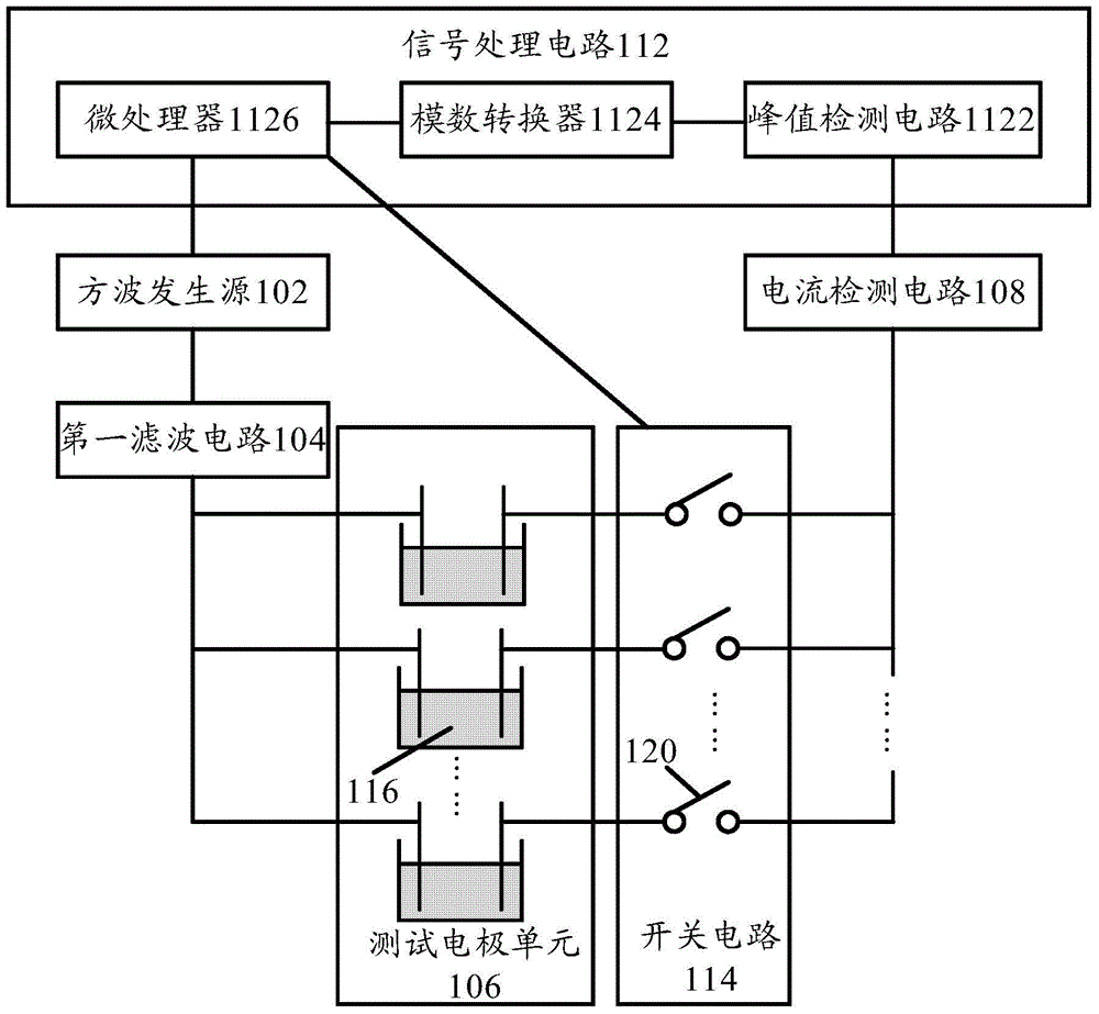
[0043] figure 1 A schematic structural diagram of a conductivity testing device according to an embodiment of the present invention is shown.

[0044] Such as figure 1 As shown, the conductivity t...


PUM


Abstract

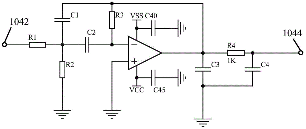
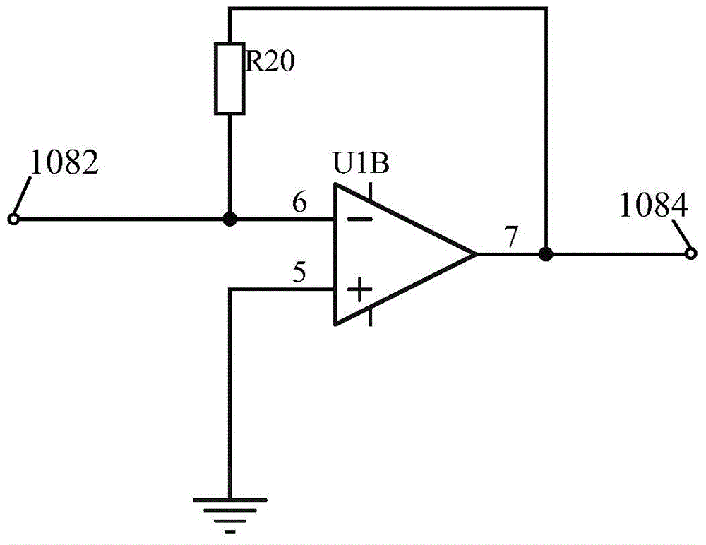
The invention provides a testing apparatus of conductivity and electrical equipment. The testing apparatus comprises a square wave generation source, a first filter circuit, a testing electrode unit, a current detection circuit, a switch circuit, and a signal processing circuit. To be specific, the square wave generation source is used for generating a square wave signal. The first filter circuit is used for carrying out filtering processing on a square wave signal to obtain a sinusoidal signal not including a direct-current component, wherein the sinusoidal signal is used as a testing voltage. The testing electrode unit includes at least three groups of testing electrodes connected in parallel and is connected to the first filter circuit; and the testing electrode unit is used for applying a testing voltage to a to-be-tested medium. The current detection circuit is used for detecting a current signal flowing through the testing electrode unit and converting the current signal into a voltage signal. The switch circuit controls a working state of each group of testing electrodes among the at least three groups of testing electrodes. The signal processing circuit determines a conductivity of a to-be-tested medium according to a voltage signal outputted by the current detection circuit. According to the technical scheme, on the premise that the testing electrode is prevented from being polarized, a conductivity of a to-be-tested medium is tested accurately and demands of different testing scenes can be satisfied.

Description

technical field [0001] The invention relates to the technical field of conductivity testing, in particular to a conductivity testing device and electrical equipment. Background technique [0002] As one of the important characteristics of substances, conductivity is widely used in material classification technology, material analysis technology, environmental protection technology and industrial production control technology because of its simple detection principle and low cost of detection devices. [0003] In the related art, the detection of conductivity is usually analyzed by using the volt-ampere characteristic curve. Specifically, a voltage signal is applied to the test electrode as an excitation signal, and the current signal flowing through the test electrode is read. According to the above-mentioned voltage signal and current signal Determine the conductivity of the analyte. However, if the DC voltage signal is used as the DC excitation signal, it will cause the p...

Claims


Application Information

Patent Timeline
Patent Type & Authority Applications(China)
IPC IPC(8): G01R27/14G01N27/04
Inventor 孟凡王新元马志海何新华张建亮陈逸凡
Owner FOSHAN SHUNDE MIDEA ELECTRICAL HEATING APPLIANCES MFG CO LTD
Learn More