
Hole pressure sealing device for coal mine drill hole and use method of device

A hole-sealing device and hole-pressing technology, which is applied in earth-moving drilling, sealing/isolation, wellbore/well components, etc., can solve the problem of increasing the gas gushing volume and gas content in the goaf, and the deformation of the cement slurry sealing section. Breaking, affecting the sealing effect, etc., to improve the sealing effect, reduce the amount of polyurethane, and ensure the effect of safe mining

Inactive Publication Date: 2016-06-08
HUAIBEI MINING IND
View PDF7 Cites 0 Cited by
  • Summary
  • Abstract
  • Description
  • Claims
  • Application Information

AI Technical Summary

Problems solved by technology

[0006] When cement slurry is used to seal the drilled holes in high-level drilling sites, after the drilling is sealed, it will be deformed due to the influence of mining and ground stress, and the cement slurry sealing section will be squeezed and broken, resulting in air leakage and affecting sealing effect
[0007] It can be seen that when cement slurry is used to seal the boreholes in the high-level drilling field, due to the impact of mining and the defects of the physical properties of the cement slurry, it will cause air leakage in the borehole and poor drainage effect, thereby increasing the gas consumption in the goaf. The amount of outflow to the working face and the gas content in the upper corner are likely to lead to safety accidents

Method used


Image

  • Hole pressure sealing device for coal mine drill hole and use method of device
  • Hole pressure sealing device for coal mine drill hole and use method of device
  • Hole pressure sealing device for coal mine drill hole and use method of device

Examples


specific Embodiment approach

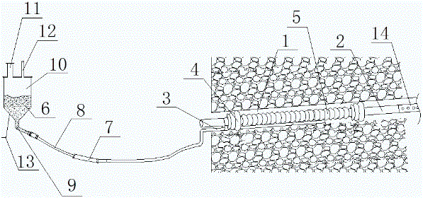
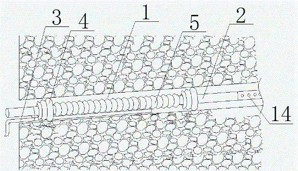
[0037] figure 1 and figure 2Show a specific embodiment of a pressure sealing device for coal mine drilling according to the present invention: the pressure sealing device for coal mine drilling includes a sealing device body with one end extending into the borehole 1, and the sealing device body includes a sealing iron Pipe 2, the side wall of the sealing iron pipe 2 is sleeved with a binding part, and the end of the binding part far away from the drill hole 1 is bound with a grouting pipe 3, and the binding part includes a fixed sponge bound at both ends of the side wall of the sealing iron pipe 2 14, between the fixed sponges 4 at both ends, there is a fixed sponge 2 5 bundled in the middle of the side wall of the sealing iron pipe 2, and the fixed sponge 4 at the end far away from the borehole 1 is bundled with a grouting pipe 3, through which the fixed sponge 1 4 and fixing sponge 2 5 can wrap a part of the side wall of the sealing iron pipe 2, reducing the gap, thereby ...


PUM


Abstract

The invention discloses a hole pressure sealing device for a coal mine drill hole and a use method of the device. The hole pressure sealing device for the coal mine drill hole comprises a hole sealing device body with one end stretching into the drill hole, and the hole sealing device body comprises a hole sealing iron pipe; the side wall of the hole sealing iron pipe is sleeved with a bundling part; and a grouting pipe is arranged in one end, away from the drill hole, of the bundling part in a bundled manner, and one end, away from the drill hole, of the grouting pipe is connected with a polyurethane container through a connecting part. The method for sealing the drill hole though the hole pressure sealing device for the coal mine drill hole comprises the steps of bundling first fixed sponges, bundling the grouting pipe into the first fixed sponges, bundling a second fixed sponge, and connecting a hole protection pipe; stretching the hole sealing iron pipe into the drill hole; using quick-setting cement for blocking an inlet of the drill hole; and connecting the grouting pipe with a rapid joint, connecting the rapid joint with a slurry outlet pipe, and connecting the slurry outlet pipe with a slurry outlet; and injecting polyurethane into the drill hole. According to the technical scheme, the hole sealing segment and the hole wall gaps of the coal mine drill hole can be effectively filled with the polyurethane, and safety is improved.

Description

technical field [0001] The invention relates to the technical field of coal mine hole sealing equipment, in particular to a pressure sealing device for coal mine drilling and a use method thereof. Background technique [0002] In coal mine production, the high-level drilling is the drilling in the wind tunnel to the coal seam roof stratum. Its main function is to use the roof cracks formed by the mining dynamic pressure of the working face as a channel to drain gas and reduce the gas in the upper adjacent layers. The possibility of rushing to the working face, at the same time, plays a role in pulling the gas in the lower part of the goaf, reducing the amount of gas gushing from the gob to the working face and the gas content in the upper corner. [0003] Factors affecting the drainage effect of high-level boreholes include: the key layer (between the caving zone and the fissure zone), the diameter of the borehole, the negative pressure of drainage, and the effective depth o...

Claims


Application Information

Patent Timeline
IPC IPC(8): E21B33/14
CPCE21B33/14
Inventor 王庆永孙淮北曹怀威董景帅
Owner HUAIBEI MINING IND
Learn More