Catalytic gasoline hydrogenation method
A technology for catalyzing gasoline and gasoline, applied in hydrotreating process, petroleum industry, processing hydrocarbon oil, etc., can solve the problem of not being a low-energy-consumption process, and achieve the effect of reducing fuel consumption, reducing heat load, and avoiding energy input
- Summary
- Abstract
- Description
- Claims
- Application Information
AI Technical Summary
Problems solved by technology
Method used
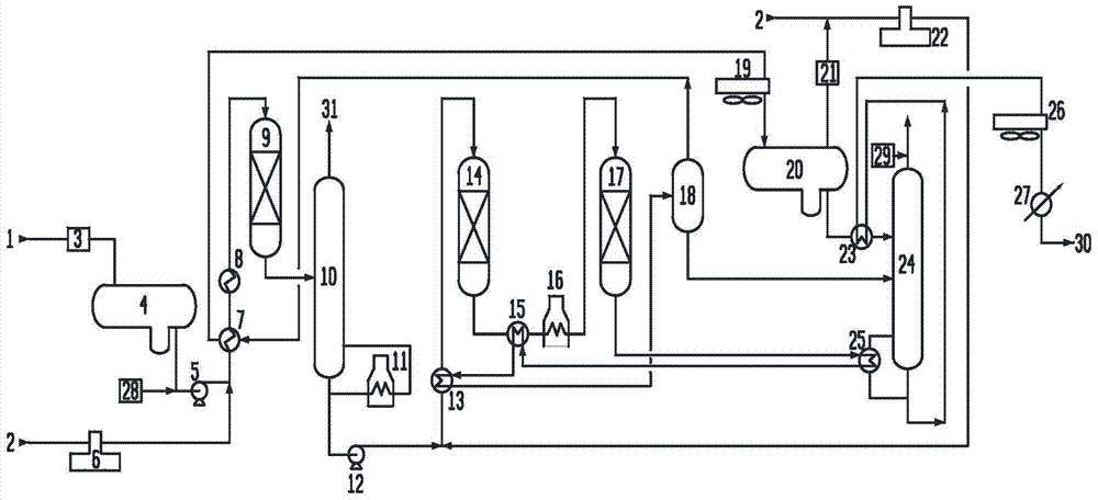
Image

Examples
Embodiment 1
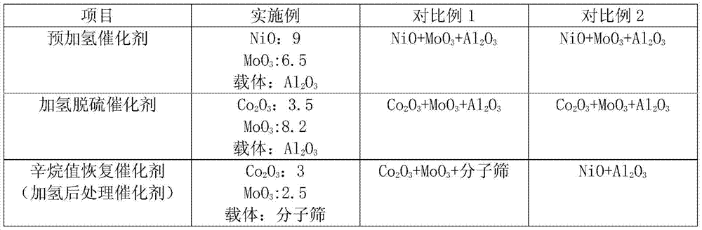
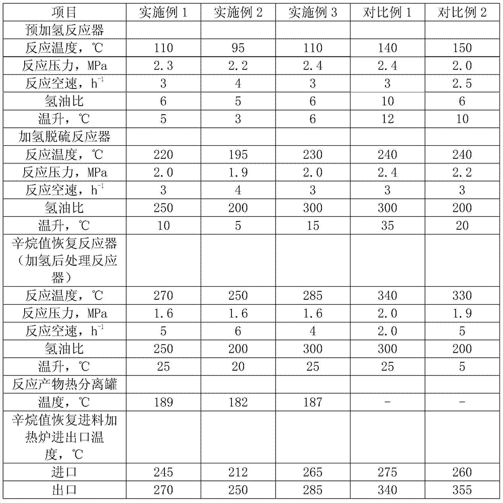
[0036] Catalyzed gasoline A is used as raw material, and its properties are shown in Table 1. The catalyst is commercially available, and its composition is shown in Table 2. The fractional distillation cut point is 70°C. See Table 3 for operating conditions, Table 4 for product properties, and Table 5 for device energy consumption. As can be seen from Table 4, the adoption of this technology can make the sulfur content in the product less than 10ppm, and the octane number loss is 1.0 units. As can be seen from Table 5, the energy consumption of the device is 15.76kgoe / t feed, which is 5.99 units lower than that of Comparative Example 1 Unit, 3.84 units lower than Comparative Example 2.
Embodiment 2
[0038] Catalyzed gasoline B is used as raw material, and its properties are shown in Table 1. The catalyst is commercially available, and its composition is shown in Table 2. The fractionation cut point is 65°C. See Table 3 for operating conditions, Table 4 for product properties, and Table 5 for device energy consumption. As can be seen from Table 4, the adoption of this technology can make the sulfur content in the product less than 10ppm, and the octane number loss is 0.5 units. As can be seen from Table 5, the energy consumption of the device is 14.95kgoe / t feed, which is 6.8 units lower than that of Comparative Example 1 Unit, 4.65 units lower than Comparative Example 2.
Embodiment 3
[0040] Catalyzed gasoline C is used as raw material, and its properties are shown in Table 1. The catalyst is commercially available, and its composition is shown in Table 2. The fractionation cut point is 60°C. See Table 3 for operating conditions, Table 4 for product properties, and Table 5 for device energy consumption. As can be seen from Table 4, the adoption of this technology can make the sulfur content in the product less than 10ppm, and the octane number loss is 1.2 units. As can be seen from Table 5, the energy consumption of the device is 15.32kgoe / t feed, which is 6.43 units lower than that of Comparative Example 1 Unit, 4.28 units lower than Comparative Example 2.
PUM
 Abstract
Description
Claims
Application Information
 - R&D
- Intellectual Property
- Life Sciences
- Materials
- Tech Scout
- Unparalleled Data Quality
- Higher Quality Content
- 60% Fewer Hallucinations
Browse by: Latest US Patents, China's latest patents, Technical Efficacy Thesaurus, Application Domain, Technology Topic, Popular Technical Reports.
© 2025 PatSnap. All rights reserved.Legal|Privacy policy|Modern Slavery Act Transparency Statement|Sitemap|About US| Contact US: help@patsnap.com