A material handling method

A treatment method and material technology, applied in special treatment targets, chemical instruments and methods, water/sludge/sewage treatment, etc., can solve problems such as low drying efficiency, poor drying effect, complex structure, etc., and achieve simple mechanism, The effect of improving space utilization

Active Publication Date: 2019-03-26
江苏易诚干燥工程有限公司
View PDF4 Cites 0 Cited by
  • Summary
  • Abstract
  • Description
  • Claims
  • Application Information

AI Technical Summary

Problems solved by technology

[0006] Therefore, the technical problem to be solved by the present invention is to overcome the defects of low drying efficiency, poor drying effect and complex structure of the material handling system in the prior art

Method used


Image

  • A material handling method
  • A material handling method
  • A material handling method

Examples


Embodiment 1

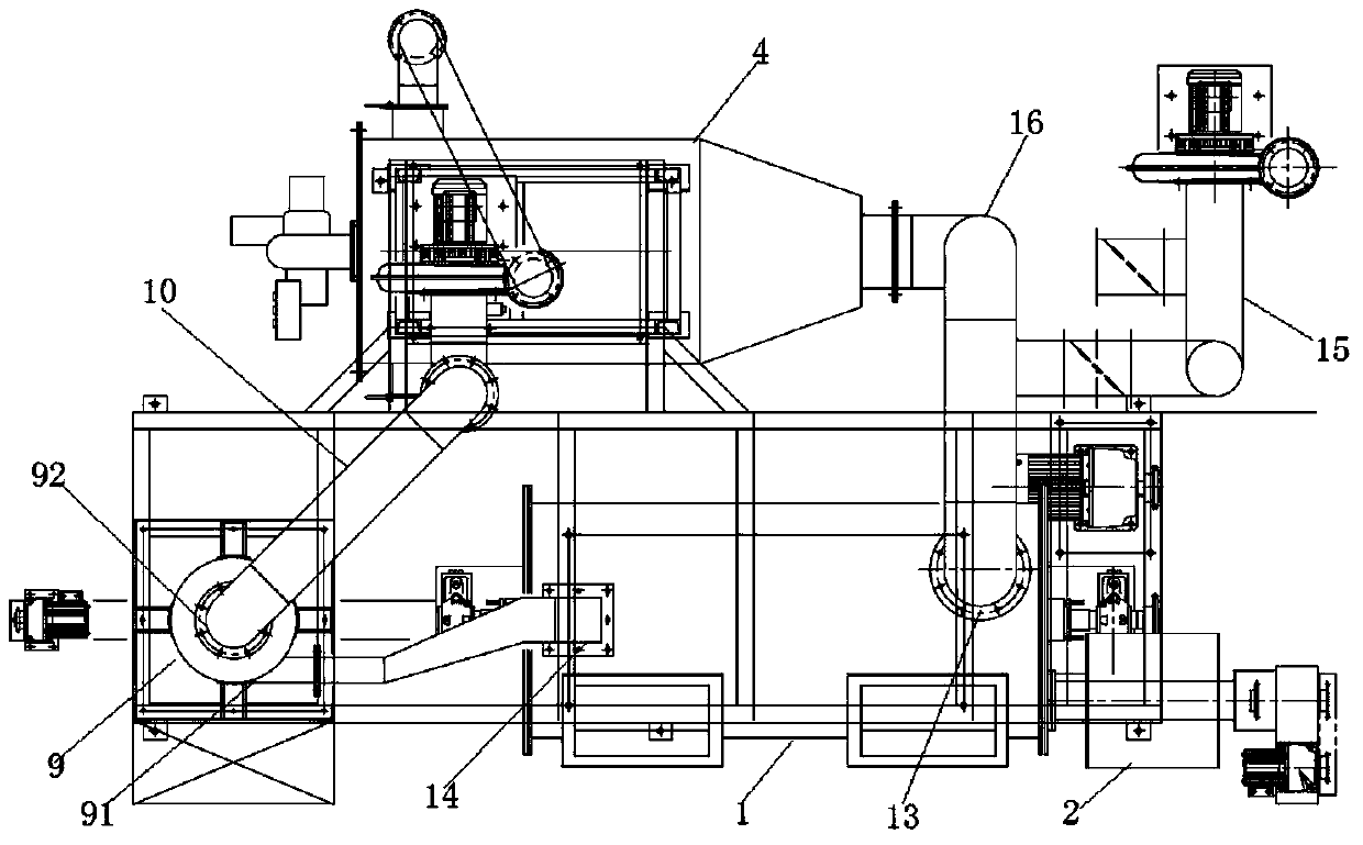
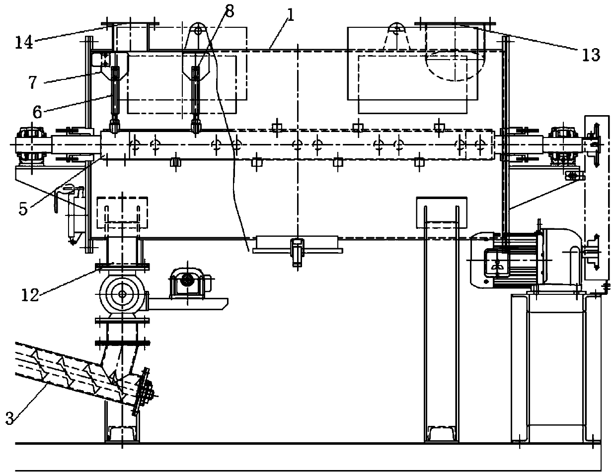
[0048] like figure 1 , this embodiment provides a material handling system comprising

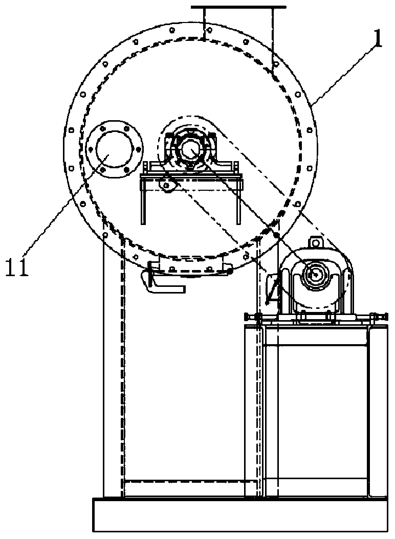
[0049] The furnace body 1 is arranged along the horizontal direction, and has a cavity, a material inlet 11 for feeding and taking out materials, and a material outlet 12; and a first air inlet 13 and a first air outlet 14 for heating gas to flow in and out;

[0050] Feeding device 2, used for adding materials into the furnace body 1;

[0051] The material receiving device 3 is used to collect the dried material in the furnace body 1;

[0052] The first rotating shaft 17 is installed in the cavity of the furnace body 1, and has an installation cavity. Several heating wires 19 are arranged on the inner wall of the installation cavity. The heating wires generate heat when they are energized. Made of thermally conductive material; such as Figure 4 shown;

[0053] The second rotating shaft 5 is sleeved on the first rotating shaft, and forms a ventilation cavity with the first rotating shaf...

Embodiment 2

[0084] This embodiment provides a material processing method, including the following steps

[0085] the step of heating the material;

[0086] The step of stirring the material;

[0087] the step of drying the material;

[0088] The heating step, the stirring step and the drying step are carried out simultaneously by using the same system, and the system is the material handling system described in Example 1.

[0089] Since the material handling system described in Embodiment 1 is used, the material handling method has any of the advantages described above.

[0090] The material treatment method is especially suitable for the treatment of sludge materials, and can be used to bond each other during the drying of the materials through a good stirring effect, so as to improve the final drying effect of the materials.

[0091] As a preferred embodiment, the caliber of the air injection port is not greater than 3mm, and the air injection speed at the air injection port is great...


PUM


Abstract

The invention relates to a material treatment method. The material treatment method adopts a material treatment system integrating heating, stirring and drying, so that heating, stirring and drying can be performed at the same time. The material treatment system integrating heating, stirring and drying comprises a furnace body, a feeding device for feeding a material into the furnace body, a material receiving device for collecting the dried material in the furnace body, a wind supply device for introducing outside hot gas into the furnace body through a first gas inlet and a stirring device for stirring and pulverizing the material, wherein the stirring device comprises a second rotating shaft which is penetrated in the cavity of the furnace body; the second rotating shaft is provided with a ventilation chamber; the ventilation chamber is provided with a plurality of gas nozzles; and the injection direction of the gas nozzles, the stirring direction of a stirring shaft and the stirring direction of blades do not coincide and are not parallel.

Description

technical field [0001] The invention relates to the technical field of material treatment, in particular to a treatment method for heating, stirring and drying materials. Background technique [0002] Sludge is the product of the sewage treatment process, which contains a large amount of organic matter, heavy metals and molds, etc. If no follow-up treatment is added, it will cause serious pollution to the environment. Therefore, it is often necessary to concentrate and dehydrate the sludge, but after this treatment The moisture content of the final sludge is usually above 70%, and the sludge needs to be further dried. [0003] The material processing system used for sludge drying in the prior art is mostly structured as the material processing system disclosed in the Chinese patent document CN201058838Y, including a furnace body, a feeder connected to the feed port of the furnace body, and a furnace body. The spray tower connected to the air outlet. Among them, the furnace...

Claims


Application Information

Patent Timeline
Patent Type & Authority Patents(China)
IPC IPC(8): C02F11/12C02F11/13C02F11/18
CPCC02F11/12C02F11/18C02F2303/06
Inventor 王良源
Owner 江苏易诚干燥工程有限公司
Why Eureka
Try Eureka